Non-pneumatic tire

a technology of non-pneumatic tires and structural supports, which is applied in the direction of tyre parts, wheel attachments, transportation and packaging, etc., can solve the problems of non-pneumatic alternatives, heavy and stiff tires, and solid tires, etc., and achieves low effective radial stiffness, high effective radial stiffness in tension, and support the mass of a vehicle

Inactive Publication Date: 2007-04-10
MICHELIN RECH & TECH SA
View PDF31 Cites 359 Cited by
  • Summary
  • Abstract
  • Description
  • Claims
  • Application Information

AI Technical Summary

Benefits of technology

[0012]The web spokes act in tension to transmit load forces between the wheel and the annular band, thus, among other functions, supporting the mass of a vehicle. Support forces are generated by tension in the web spokes not connected to the ground-contacting portion of the annular band. The wheel or hub can be said to hang from the upper portion of the tire. Preferably, the web spokes have a high effective radial stiffness in tension and a low effective radial stiffness in compression. The low stiffness in compression allows the web spokes attached to the ground-contacting portion of the annular band to bend for absorbing road shocks and for better conforming the annular band to the irregularities in the road surface.
[0013]The web spokes also transmit the forces required for accelerating, stopping, and cornering. The arrangement and orientation of the web spokes can be selected ...

Problems solved by technology

Conventional non-pneumatic alternatives, for example, solid tires, spring tires, and cushion tires lack the performance advantages of pneumatic tires.
These types of tires can be heavy and stiff and lack the shock absorbing capability of pneumatic tires.
When made more resilient, conventional non-pneumatic ti...

Method used


Image

  • Non-pneumatic tire
  • Non-pneumatic tire
  • Non-pneumatic tire

Examples


Embodiment Construction

[0034]The following terms are defined as follows for this description:

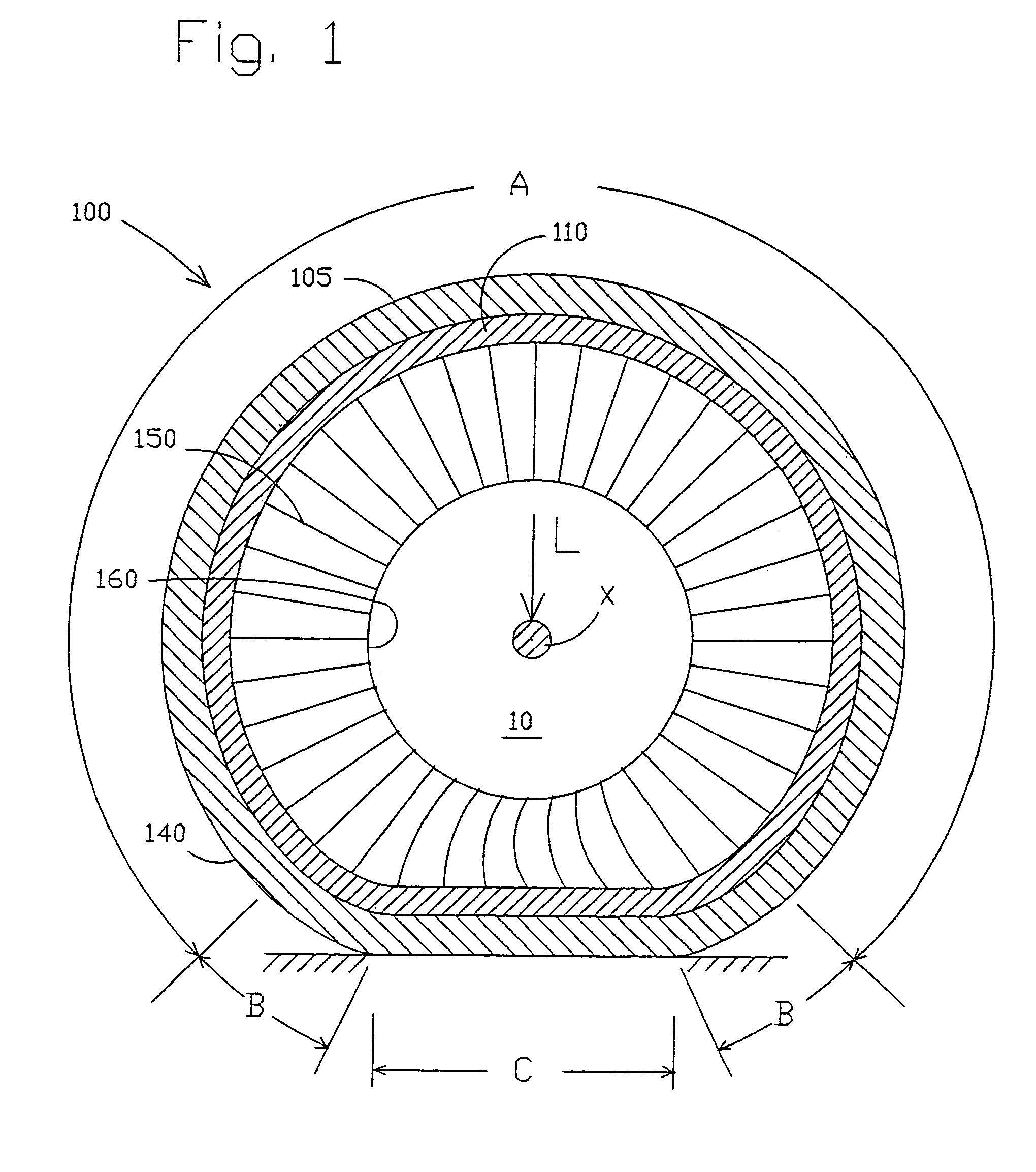
[0035]“Equatorial Plane” means a plane that passes perpendicular to the tire axis of rotation and bisects the tire structure.

[0036]“Meridian Plane” means a plane that passes through and includes the axis of rotation of the tire.

[0037]“Modulus” of elastomeric materials means the tensile modulus of elasticity at 10% elongation measured per ASTM Standard Test Method D412.

[0038]“Modulus” of the membranes means the tensile modulus of elasticity at 1% elongation in the circumferential direction multiplied by the effective thickness of the membrane. This modulus can be calculated by Equation 1, below, for conventional tire steel belt materials. This modulus is noted with a prime (′) designation.

[0039]“Shear Modulus” of elastomeric materials means the shear modulus of elasticity and is defined equivalent to one-third the tensile modulus of elasticity as defined above for elastomeric materials.

[0040]“Hysteresis” means the ...


PUM


Abstract

A structurally supported tire includes a ground contacting tread portion, a reinforced annular band disposed radially inward of the tread portion, and a plurality of web spokes extending transversely across and radially inward from the reinforced annular band and anchored in a wheel or hub. The reinforced annular band comprises an elastomeric shear layer, at least a first membrane adhered to the radially inward extent of the elastomeric shear layer and at least a second membrane adhered to the radially outward extent of the elastomeric shear layer. Each of the membranes has a longitudinal tensile modulus sufficiently greater than the shear modulus of the shear layer so that when under load the ground contacting portion of the tire deforms to a flat contact region through shear strain in the shear layer while maintaining constant the length of the membranes, the web spokes transmitting load forces between the annular band and the hub through tension in the web spokes not connected to the ground contacting portion of the tire.

Description

[0001]This is a continuation of PCT Application No. PCT / US01 / 26379 filed on Aug. 24, 2001 and a continuation-in-part of U.S. application Ser. No. 10 / 081,571 filed on Feb. 22, 2002, now U.S. Pat. No. 6,769,465 issued Aug. 3, 2004.BACKGROUND AND SUMMARY OF THE INVENTION[0002]The invention relates to a non-pneumatic, structurally supported tire. More particularly, the invention relates to a non-pneumatic tire that supports a load with its structural components and has pneumatic tire-like performance capabilities to serve as a replacement for pneumatic tires.[0003]The pneumatic tire has capabilities in load carrying, road shock absorption, and force transmission (accelerating, stopping, and steering) that make it the preferred choice for use on many vehicles, most notably, bicycles, motorcycles, automobiles, and trucks. These capabilities have also been highly advantageous in the development of the automobile and other motor vehicles. Pneumatic tire capabilities in shock absorption are ...

Claims


Application Information

Patent Timeline
IPC IPC(8): B60B9/26B60B9/04B60C7/00B60C7/10B60C7/12B60C7/14B60C7/18B60C7/22B60C9/18B60C9/20
CPCB60B9/04B60B9/26B60C7/00B60C7/14B60C7/10B60C7/22B60C9/18B60C9/20B60C7/18Y10T152/1018
Inventor RHYNE, TIMOTHY B.THOMPSON, RONALD H.CRON, STEVEN M.DEMINO, KENNETH W.
Owner MICHELIN RECH & TECH SA
Why Eureka
Try Eureka