Orthopedic knee brace

a knee brace and orthopaedic technology, applied in the field of orthopaedic knee braces, can solve the problems of ineffective commercially, lack of panel size, orientation and structural integrity, and inability to disperse mechanical pressure on the leg and support body mass, and achieve the effect of reducing the stress on the knee compartmen

Inactive Publication Date: 2018-03-01
HUMPHREY JAY C
View PDF6 Cites 5 Cited by
  • Summary
  • Abstract
  • Description
  • Claims
  • Application Information

AI Technical Summary

Benefits of technology

[0031]Accordingly, it is a principal object of this invention to provide an orthopedic knee brace fuselage w

Problems solved by technology

However, more powerful systems capable of supporting body mass have been to date, ineffective from a commercial standpoint.
Without rigid panels fixed to the main frame, US Published Application No. 2013/0038056 lacks the panel size, orientation and structural integrity needed to disperse mechanical pressure on the leg and support body mass.
The three prior art examples, however, still encircle the leg with straps and do not function beyond what prior prophylactic knee braces are capable of.
They cannot produce high levels of resistance without drastically reducing leg circulation.
The flex rod motion control system has limited adjustability and the boot interface is rear mounted resulting in improper boot shell flex and loss of compliance between the lower leg and boot.Ski Mojo—This system utilizes a rear facin

Method used


Image

  • Orthopedic knee brace
  • Orthopedic knee brace
  • Orthopedic knee brace

Examples


Embodiment Construction

[0046]Detailed descriptions of the preferred embodiments are provided herein. It is to be understood, however, that the present invention may be embodied in various forms.

[0047]Therefore, specific details disclosed herein are not to be interpreted as limiting, but rather as a basis for the claims and as a representative basis for teaching one skilled in the art to employ the present invention in virtually any appropriately detailed system, structure or manner.

[0048]While the invention has been described in connection with or more preferred embodiments, it is not intended to limit the scope of the invention to the particular form set forth. On the contrary, it is intended to cover such alternatives, modifications, and equivalents as may be included with the spirit and scope of the invention as defined by the appended claims.

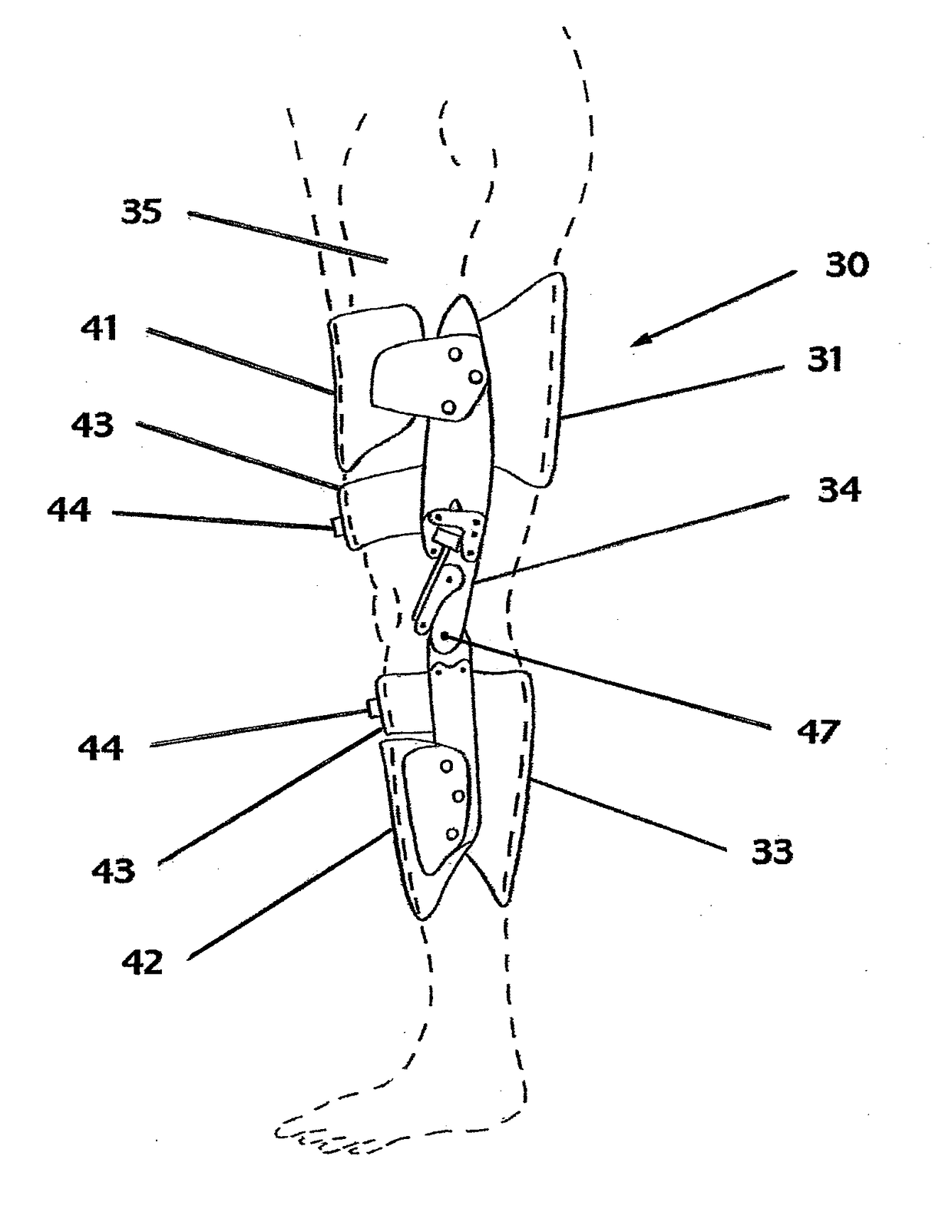
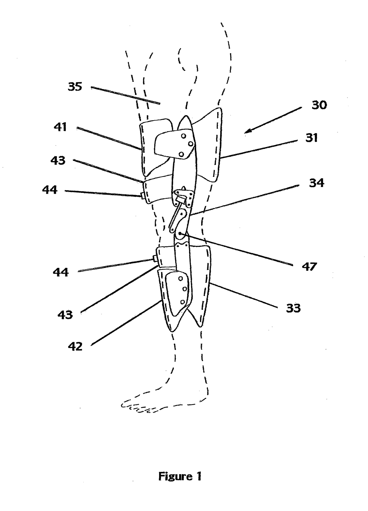
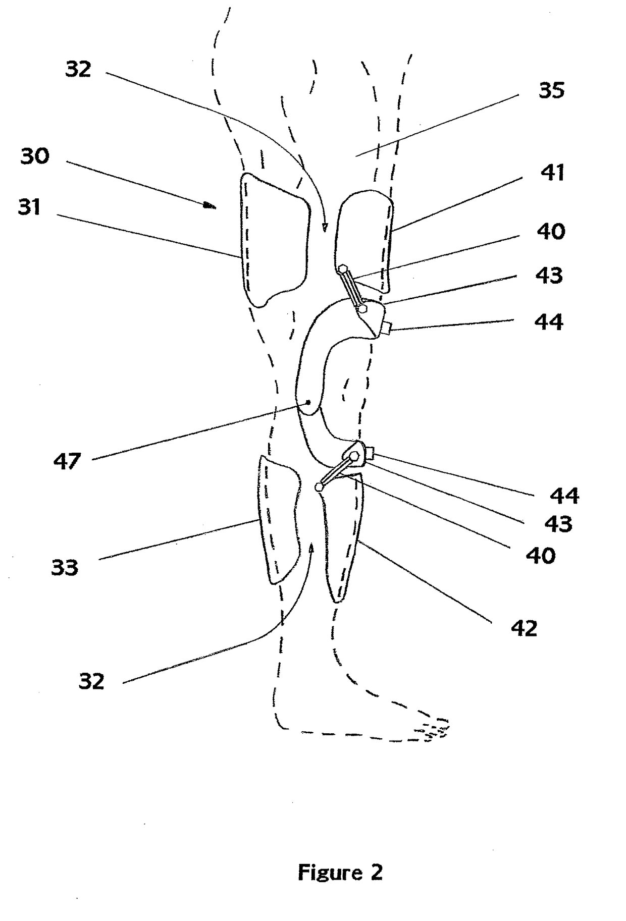
[0049]Reference is now made specifically to the drawings in which identical or similar parts are designated by the same reference numerals throughout.

[0050]Referr...


PUM


Abstract

An apparatus that includes a composite fuselage and motion control system designed to protect the human leg from knee pain and muscular fatigue created by repetitive vertical movement or extended periods of squatting. Fuselage panels and frame encapsulate the leg and functionally integrate with hard shell boots to create a rigid exoskeleton structure that resists radial displacement of the knee or ankle. The fuselage ‘open clamshell’ leg harness utilizes wide composite body panels that disperse pressure across a large surface area, allowing the harness to provide body mass support and device securement without restriction of the body's circulatory system.

Description

BACKGROUND OF INVENTION[0001]This invention relates to orthopedic knee braces and, more specifically, to an apparatus that supports body mass and alleviates knee compartment stress through mechanical assistance. The present application consists of: a composite panel fuselage that encapsulates the leg; a motion control mechanism that supports body mass by managing flexion of the leg; and a lower support harness that integrates with hard shell boots. Main performance features of the present invention include enhanced impact protection, increased stabilization of the leg, mitigation of knee compartment stress and increased muscular efficiency.[0002]Overuse, injury and age take their toll on a person's knees, degradation of cartilage and synovial fluid, known as Plica syndrome, is inevitable. Orthotic articulating (OA) knee braces that develop low levels of resistance to flexion have had some success in rehabilitation, preventive care and sports markets. However, more powerful systems c...

Claims


Application Information

Patent Timeline
IPC IPC(8): A61F5/01
CPCA61F5/0125A61F2005/0197A61F2005/0167
Inventor HUMPHREY, JAY C.
Owner HUMPHREY JAY C
Why Eureka
Try Eureka