Illumination system and display device
- Summary
- Abstract
- Description
- Claims
- Application Information
AI Technical Summary
Benefits of technology
Problems solved by technology
Method used
Image

Examples
Embodiment Construction
[0017]In the description and claims of the present invention, design rules for placing light emitters in a backlight illumination system are given resulting in a light and color distribution of the light emitted by the backlight illumination system with improved uniformity. In the known backlight illumination system, the placement of the light emitters is symmetrical with respect to an imaginary plain perpendicular to the line along which the individual light emitters are placed. Such a symmetric placement of the light emitters poses a restriction on the assignment of the light emitters in the backlight illumination system resulting in a less than configuration of the light emitters in the backlight illumination system.
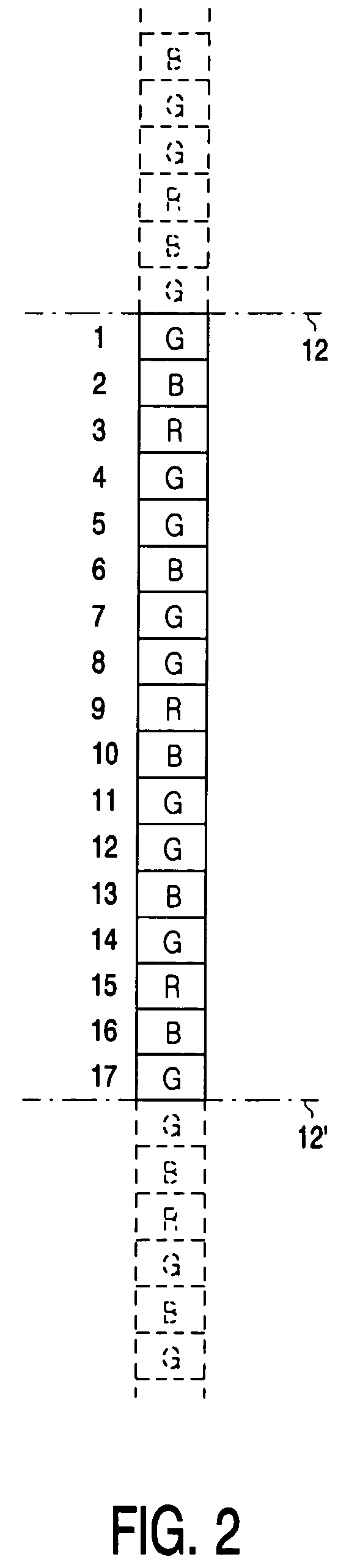
[0018]According to embodiments of the invention, there are N positions for placing the light emitters. By way of example, a backlight illumination system comprising three kinds of light emitters is considered, i.e. red (R) light emitters, green (G) light emitters and ...
PUM
 Abstract
Description
Claims
Application Information