Punch for hydroforming die

a technology of hydroforming die and punching machine, which is applied in the field of hydroforming machine, to achieve the effects of improving the quality of the opening, reducing the number of slugs, and improving the sealing ability

Inactive Publication Date: 2007-04-17
GM GLOBAL TECH OPERATIONS LLC
View PDF12 Cites 8 Cited by
  • Summary
  • Abstract
  • Description
  • Claims
  • Application Information

AI Technical Summary

Benefits of technology

[0008]One advantage of the present invention is that a punch is provided for a hydroforming die having greater sealing ability. Another advantage of the present invention is that the punch improves the quality of an opening created in a tubular member during hydroforming. Yet another advantage of the present invention is that the punch provides better slug retention during hydroforming. Still another advantage of the present invention is that the punch provides cleaner piercing through the material of the tubular member. A further advantage of the present invention is that the punch aids in sustaining water pressure as it pierces during hydroforming. Yet a further advantage of the present invention is that the punch results in less down time in the hydroforming process. Still a further advantage of the present invention is that the punch results in significant improvement in scrap reduction during hydroforming. Another advantage of the present invention is that the punch reduces the cost of hydroforming.
[0009]Other features and advantages of the present invention will be readily appreciated, as the same becomes better understood, after reading the subsequent description taken in conjunction with the accompanying drawings.

Problems solved by technology

Any small variation in hydraulic cylinder oil flow, forming pressure, hydraulic cylinder oil pressure, wall thickness, or hardness will interfere with the timing in hydraulic cylinder movement, thereby allowing some openings to be pierced before or after the programmed sequence.
This ultimately contributes to uncontrolled leakage areas, which will contribute to non-repeatable tubular member definition and in most cases to the complete collapse of the tubular member resulting in scrap.

Method used


Image

  • Punch for hydroforming die
  • Punch for hydroforming die
  • Punch for hydroforming die

Examples


Embodiment Construction

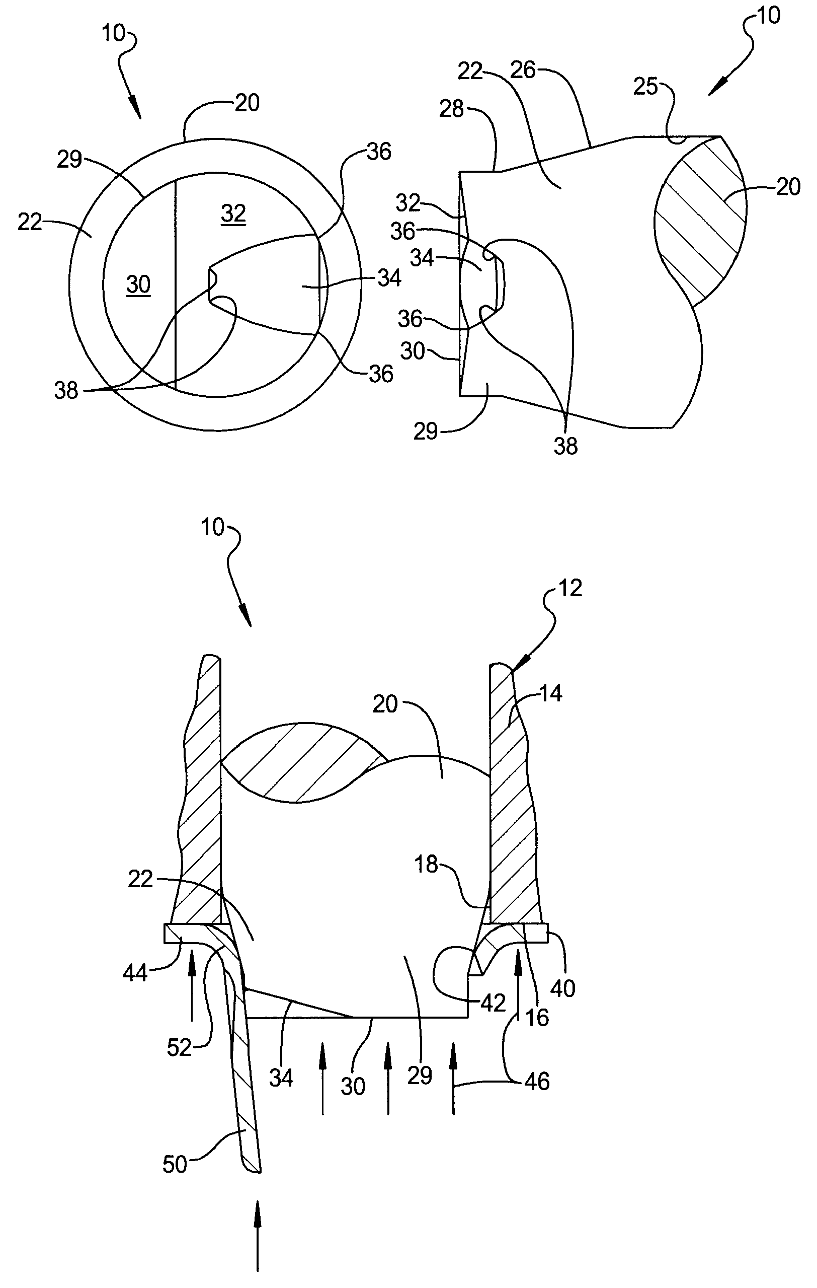
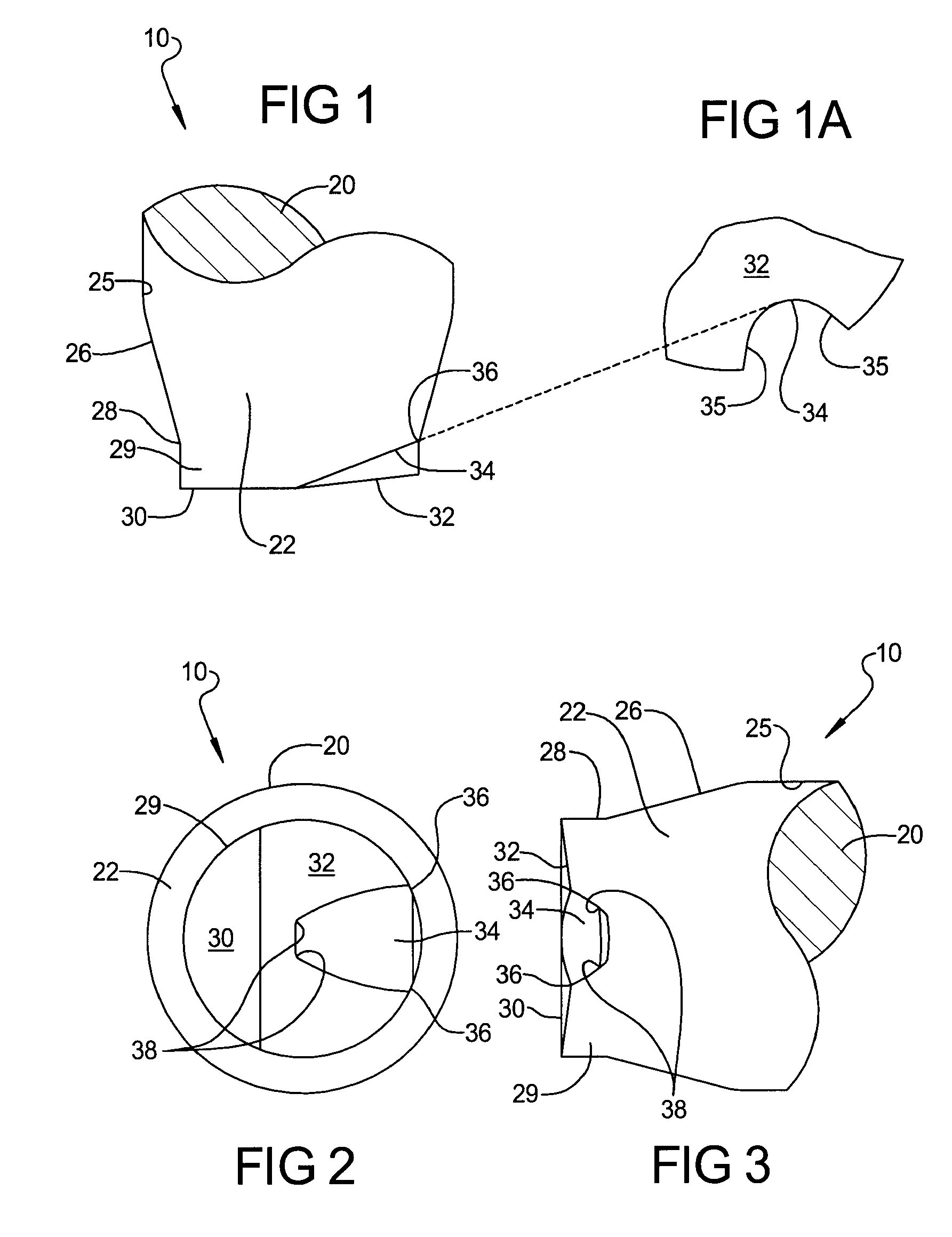
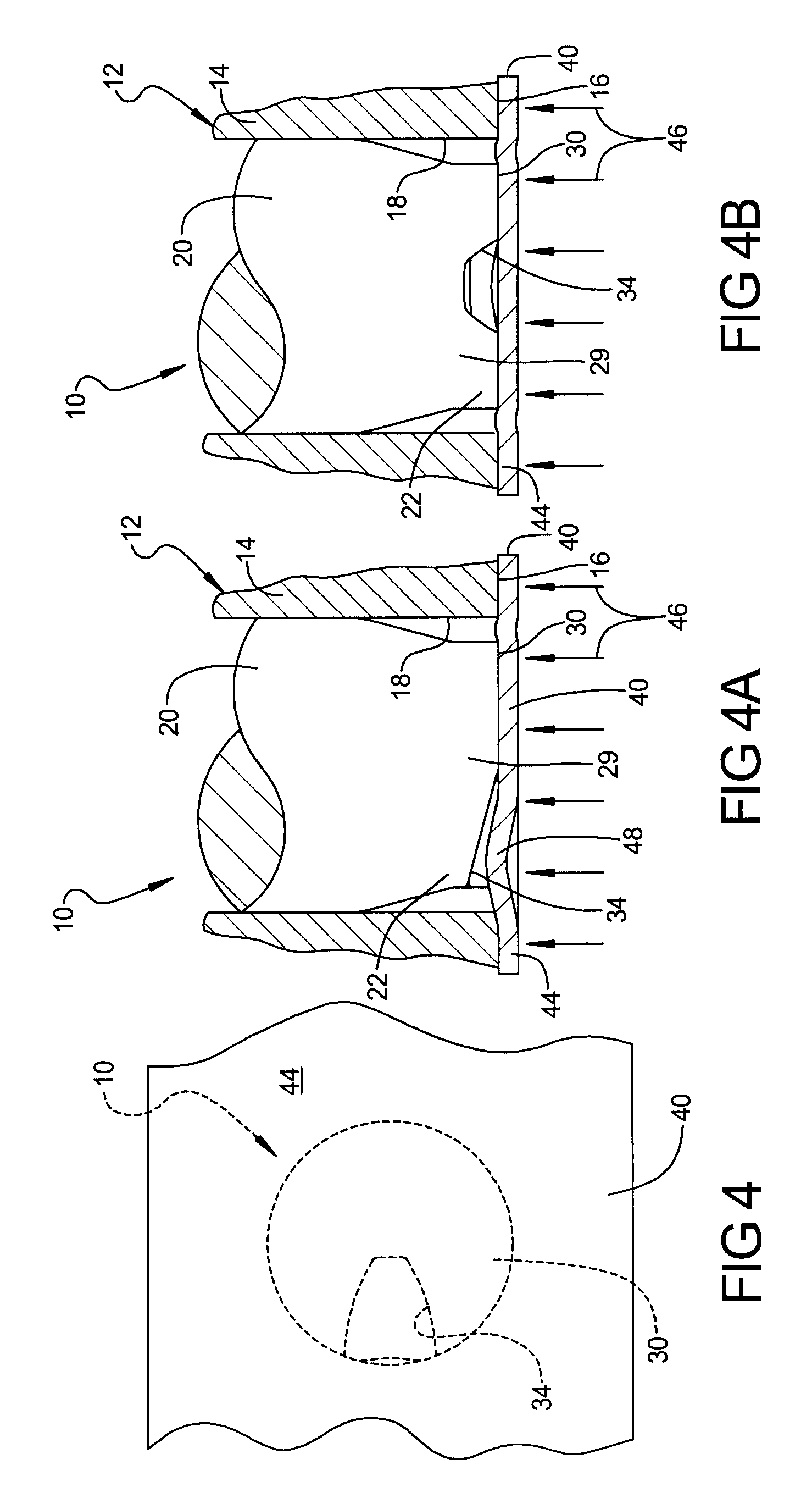
[0029]Referring to the drawings and in particular FIG. 1, one embodiment of a punch 10, according to the present invention, is generally shown for a hydroforming die, generally indicated at 12 and partially shown in FIGS. 4A and 4B. The hydroforming die 12 is a die set comprised of a lower die half and an upper die half, only one of which is shown at 14. The die half 14 includes a tubular forming cavity portion 16 (partially shown). The die half 14 includes a cavity 18 extending axially from the tubular forming cavity portion 16 for the punch 10 to be described.

[0030]The punch 10 includes a body 20 disposed within the cavity 18 of the die half 14. The body 20 extends axially and is generally cylindrical in shape. The body 20 has a generally circular cross-sectional shape and a predetermined diameter. In one embodiment, the body 20 has a predetermined diameter of twenty-seven millimeters (27 mm).

[0031]The punch 20 also includes a neck 22 extending axially from the body 20. The neck 2...


PUM

PropertyMeasurementUnit
pressureaaaaaaaaaa
diameteraaaaaaaaaa
inner radiusaaaaaaaaaa

Abstract

A punch for a hydroforming die includes a body, a neck extending axially from the body, a head extending axially from the neck and having a diameter less than a diameter of the body and a thumbnail slot extending axially and radially into the head to allow fluid within a tubular member to force a wall portion of the tubular member outward into the slot of the punch and be sheared by the punch to produce an opening in the tubular member.

Description

TECHNICAL FIELD[0001]The present invention relates generally to hydroforming and, more specifically, to a punch for a hydroforming die.BACKGROUND OF THE INVENTION[0002]It is known to form a cross-sectional profile of a tubular member by a hydroforming process in which a fluid-filled tubular member is placed within a cavity of a die and then the die is closed so that the tubular member is pinched within the die. Fluid pressure is then increased inside the tubular member to expand the tubular member outwardly against the cavity of the die to provide a tubular member having a die formed cross-sectional profile.[0003]During tube hydroforming, large size punches of various shapes are used to create desired openings in the tubular member by piercing. The large punches currently used, necessitate similarly large activating hydraulic cylinders in order to overcome the forces needed for piercing. Large bore hydraulic cylinders need high volume of oil flow to operate.[0004]Using the hydroform...

Claims


Application Information

Patent Timeline
Patent Type & Authority Patents(United States)
IPC IPC(8): B21D28/28B21D26/02
CPCB21D28/10B21D28/28Y10T83/0443Y10T83/0591Y10T83/0596
Inventor GHIRAN, MIKE M.NG, SUSAN
Owner GM GLOBAL TECH OPERATIONS LLC
Why Eureka
Try Eureka