Apparatus and method for fatigue testing

a fatigue testing and apparatus technology, applied in the direction of tensile/compressive force, instruments, mechanical means, etc., can solve the problems of difficult to achieve blade aerofoil shape and blade root shape, and the behaviour of specimens that do not accurately reflect the behaviour of real blades

Active Publication Date: 2007-04-17
ROLLS ROYCE PLC
View PDF20 Cites 36 Cited by
  • Summary
  • Abstract
  • Description
  • Claims
  • Application Information

AI Technical Summary

Benefits of technology

[0011]Accordingly the present invention seeks to provide a novel apparatus and method for the f

Problems solved by technology

These LCF and HCF stresses have a detrimental effect on the integrity of the blades.
The fatigue testing of materials under conditions representative of gas turbine operating conditions is difficult to achieve for blade aerofoil shapes and blade root shapes.
It is known to perform tests on specimens representative of blade shapes, but the behaviour of these specimens does not accurately reflect the behaviour of real blades.
During service operation, the rotor blade assembly is subject to a complex loading system, comprising centripetal load, gas load and vibration.
Rotation of the fan assembly results in a large load on the dovetail root, due to centripetal acceleration, as the blade tries to pull out of the retention slot.
In addition, as the fan blade compresses the incoming air, the pressure differential across the blade causes the aerofoil to bend, imparting an additional bending load into the dovetail root.
Under the action of these loads, sliding occurs between the blade and di

Method used


Image

  • Apparatus and method for fatigue testing
  • Apparatus and method for fatigue testing
  • Apparatus and method for fatigue testing

Examples


Embodiment Construction

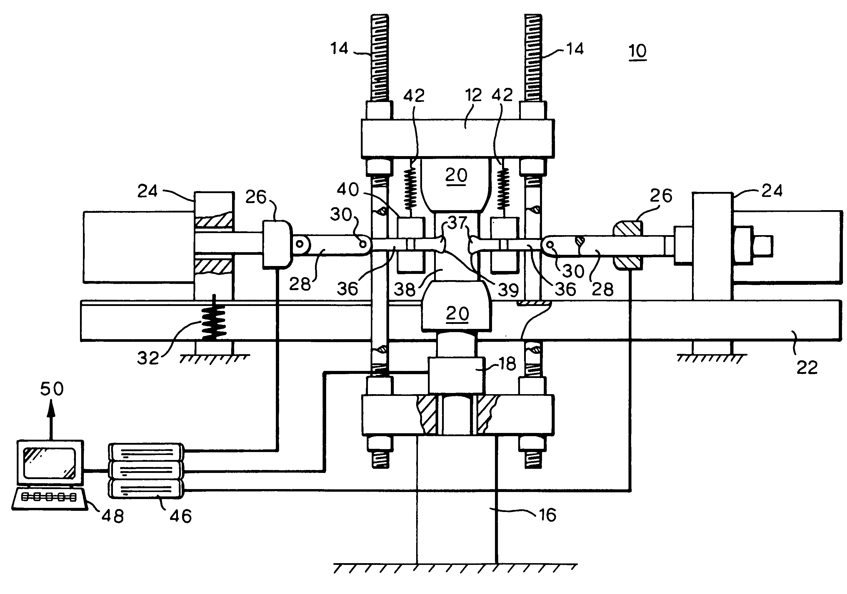
[0029]Referring first to FIG. 1, a test machine shown generally at 10 has a load frame 12. Pillars 14 support a first hydraulic actuator 16 and a first load cell 18, and a pair of grips 20. Further structure 22 supports second hydraulic actuators 24, second load cells 26 and a pair of loading bars 28. Each loading bar 28 has a hole 30 near its end, into which a pin (not shown) can be fitted.

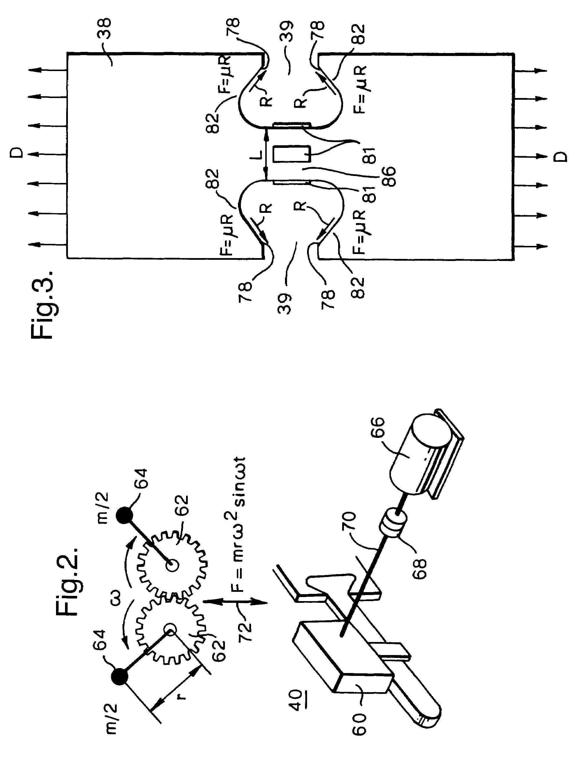
[0030]A fixture 38 is securely held between the grips 20 of the testing machine 10. The fixture 38 has two recesses 39 matching the profile of the disc slots whose behaviour is to be reproduced.

[0031]Two test specimens 36 have, at one end, a mounting feature 37 matching the profile of the blade whose behaviour is to be reproduced and, at the other end, a suitable hole permitting pin attachment of the test specimens 36 to the loading bars 28, in the conventional manner.

[0032]In operation, the first actuator 16 applies a load to the fixture 38. The applied load is measured by the first load cell 18...


PUM


Abstract

A method of simulating life of a rotor blade mounting feature mounted in a complementary rotor disc mounting feature comprises the steps of providing two specimen mounting features (37) each having portions defining pressure faces matching in profile respective faces of the rotor blade mounting feature; providing a fixture (38) having two opposed mounting features (39) each having portions defining pressure faces (78) matching in profile respective faces of the rotor disc mounting feature; mounting the specimen mounting features (37) in the fixture mounting features (39); applying a first load to the specimen mounting features (37); measuring a strain in a region (86) of the fixture (38) between the fixture mounting features (39); applying a second load to the fixture (38), the second load being substantially perpendicular to the first load; and controlling the second load in response to the measured strain. A high cycle load may simultaneously be applied to the specimen mounting features (37). Claims are also included for an apparatus (10) for carrying out the method.

Description

FIELD OF THE INVENTION[0001]This invention relates to fatigue testing of materials, and more particularly relates to an apparatus and method for simulating fatigue of rotor blade roots in complementary rotor blade slots.BACKGROUND OF THE INVENTION[0002]Gas turbine engine fan blades, compressor blades and turbine blades are subjected to a combination of low cycle fatigue (LCF) and high cycle fatigue (HCF) stresses during the engine's operation. These LCF and HCF stresses have a detrimental effect on the integrity of the blades. The LCF stresses result from the centripetal force experienced by the blades as they rotate about the engine axis. The HCF stresses result from aerodynamic and other vibration excitation of the blades.[0003]In order to design fan blades, compressor blades and turbine blades that are resistant to fatigue, a good understanding is required of the combination of the steady and alternating stresses to which a blade may be subjected in operation.[0004]The fatigue te...

Claims


Application Information

Patent Timeline
IPC IPC(8): G01N3/00G01N3/04G01N3/32
CPCG01N3/32G01N2203/0073G01N2203/027G01N2203/0464
Inventor WOODWARD, COLIN JMCELHONE, MARTINCRABTREE, JAMES SGREENACRE, PAUL A
Owner ROLLS ROYCE PLC
Why Eureka
Try Eureka