
Image forming device and image forming system having a replacement unit mounted therein

a technology of image forming and replacement unit, which is applied in the direction of instruments, electrographic process equipment, optics, etc., can solve the problems of lowering image quality and inability to guarantee operations, and achieve the effect of maintaining convenience for users

Inactive Publication Date: 2007-04-17
FUJIFILM BUSINESS INNOVATION CORP
View PDF14 Cites 19 Cited by
  • Summary
  • Abstract
  • Description
  • Claims
  • Application Information

AI Technical Summary

Benefits of technology

The invention provides an image forming device and system that can use a replacement unit, even if it is not a genuine product. The device and system allow users to select an operation mode that matches the replacement unit, and display information about the usage of the replacement unit in a way that is convenient for the user. This ensures that users can use the replacement unit without mistakenly identifying it as a genuine product, while still maintaining the convenience and utility of the system.

Problems solved by technology

Meanwhile, when a unit that is replaced by the user is a product other than a genuine product for the image forming device, problems, such as a lowering of the image quality and other cases of inadequate exhibition of the performance of the image forming device, the inability to guarantee operations, and malfunctions, etc., may occur.

Method used


Image

  • Image forming device and image forming system having a replacement unit mounted therein
  • Image forming device and image forming system having a replacement unit mounted therein
  • Image forming device and image forming system having a replacement unit mounted therein

Examples


first embodiment

[0069]A description is given of an embodiment of the invention based on the drawings.

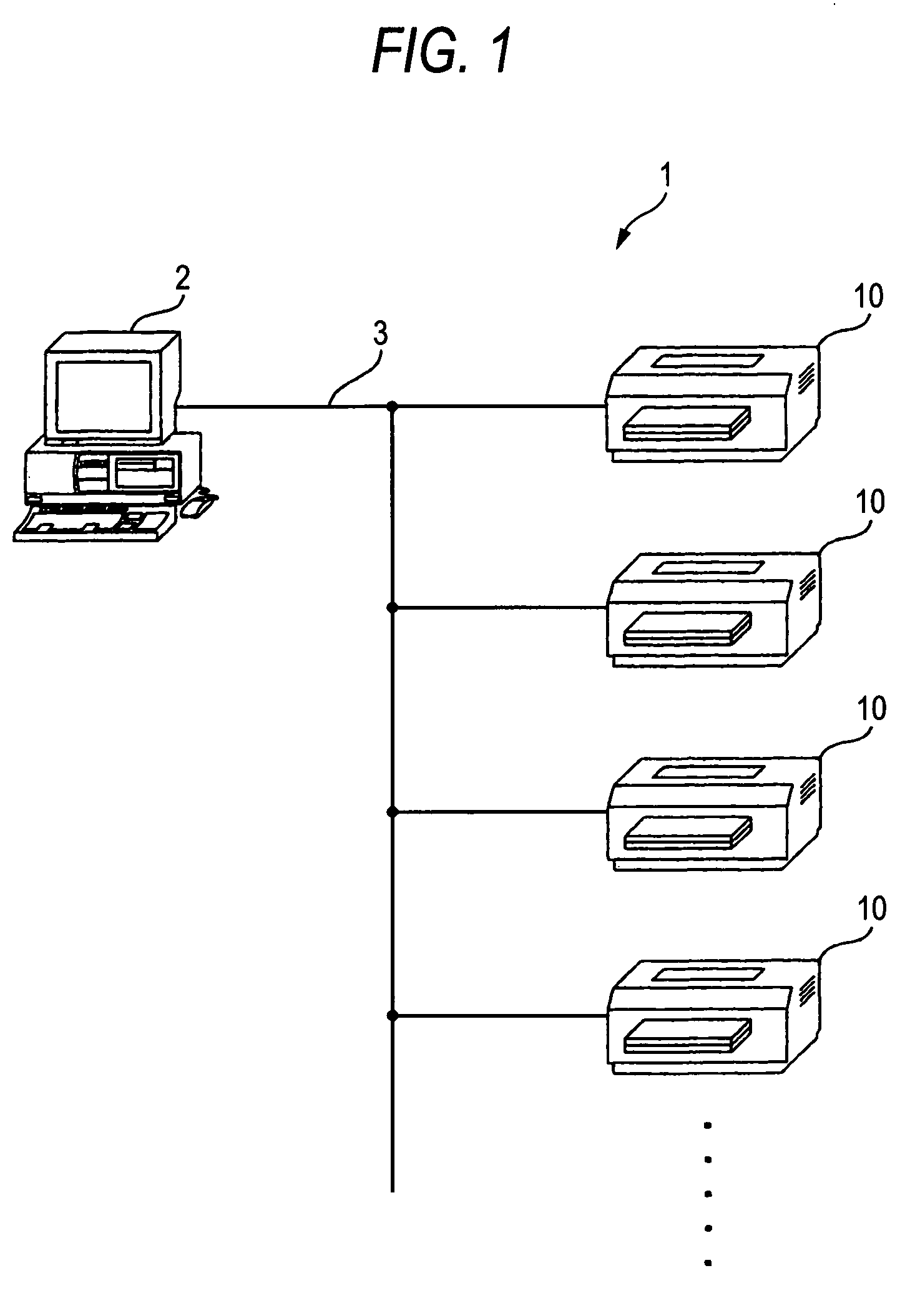
[0070]FIG. 1 shows an image forming system 1 of an embodiment according to the invention. The image forming system 1 is arranged by a PC (Personal Computer) or other host device 2 being connected, for example, to a plurality of image forming devices 10 via a network 3. The host device 2 may, for example, be a control device, such as an MCU (Micro Controller Unit), etc., an input / output device, such as a touch panel, or a terminal besides a PC, which has a communication device for sending and receiving signals via the network 3. The network 3 may be wired or wireless. Also, a plurality of host devices 2 maybe connected to the network 3.

[0071]The image forming system 1 is thus arranged so that the host device 2 can control the image forming devices 10 via the network 3.

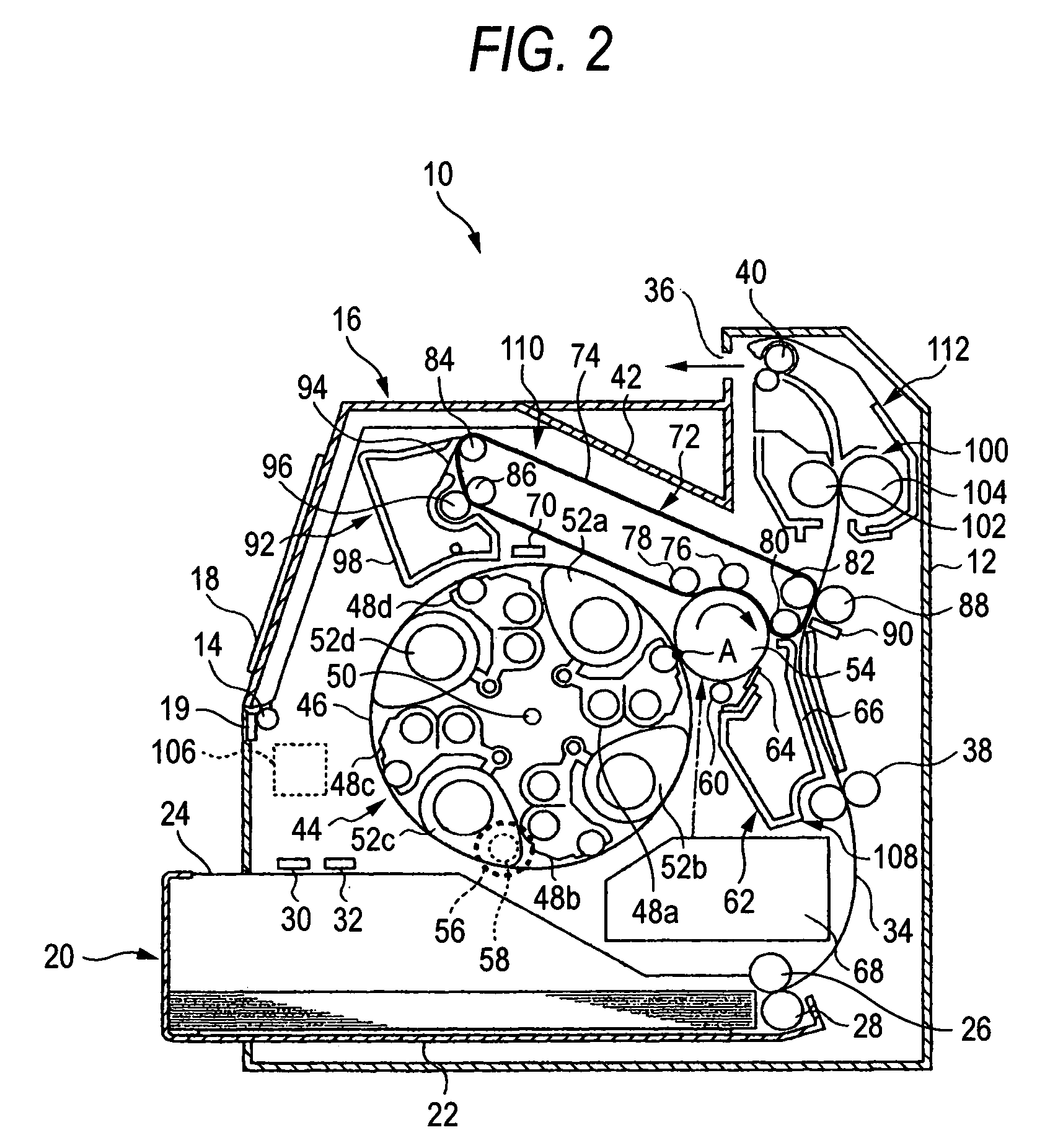
[0072]FIG. 2 shows an image forming device 10 in outline. The image forming device 10 has an image forming device main body 12, and an...

second embodiment

[0222]An image forming device and an image forming system of the second embodiment includes configurations of the first embodiment that are explained by FIGS. 1 to 27. Therefore, in this embodiment, explanations of the overlapped configurations are omitted.

[0223]In this embodiment, a description is given of control of an image forming device 10 based on data stored in a storage unit 204 and a main unit NVM 184.

[0224]Based on the data stored in the storage unit 204 and main unit NVM 184, the image forming device 10 controls display made by the UI device 18. For example, on the basis of control by the CPU 202, the UI device 18 displays the remaining quantity of toner when the toner cartridge 52 is genuine, and displays the use quantity of toner when the toner cartridge 52 is other than a genuine cartridge. This is because, where the toner cartridge is other than a genuine cartridge, the remaining quantity of toner cannot be calculated since the toner quantity is not clear.

[0225]Next, ...


PUM


Abstract

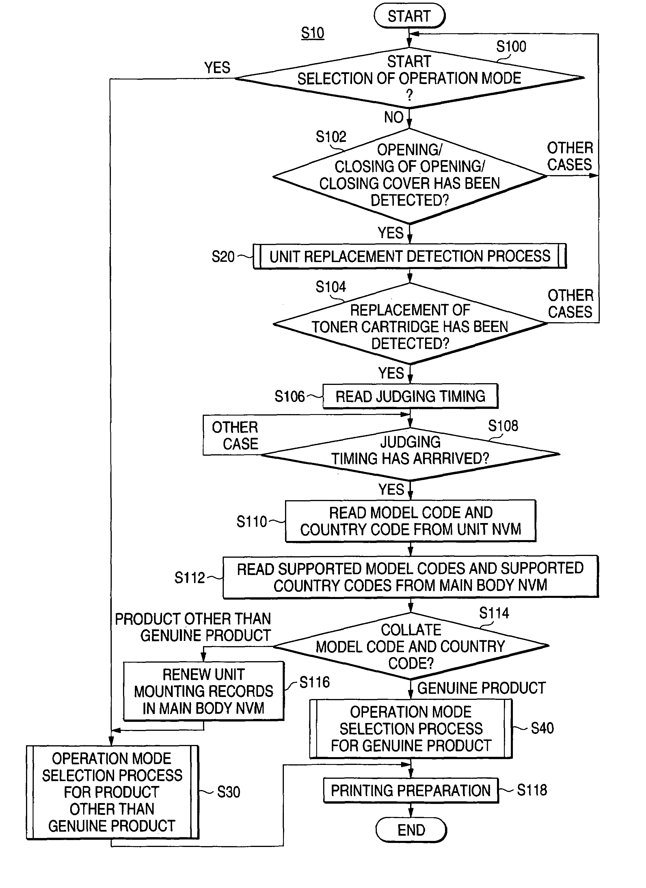
Where a toner cartridge other than a genuine product is mounted, the image forming device stops displaying information regarding the usage amount such as the residual amount of toner, etc., and causes the display / input device of the host device to display a screen including information regarding an operation mode and a toner cartridge other than a genuine product. In addition, the image forming device not only stops displaying the residual amount of toner, but also causes the display / input device of the host device to display a screen including information regarding the number of sheets of paper already printed, which is measured or metered from the mounting of a toner cartridge, and the printing coverage thereof.

Description

BACKGROUND OF THE INVENTION[0001]1. Field of the Invention[0002]The present invention relates to an image forming device and an image forming system, and in particular those having a replacement unit mounted therein.[0003]2. Background Art[0004]There are known image forming devices, with which consumables and other units can be replaced at a user's option.[0005]Meanwhile, when a unit that is replaced by the user is a product other than a genuine product for the image forming device, problems, such as a lowering of the image quality and other cases of inadequate exhibition of the performance of the image forming device, the inability to guarantee operations, and malfunctions, etc., may occur. This is because an image forming device controls the image forming process in consideration of the characteristics of the toner, the characteristics of the image carrying body, the charging voltage, the cleaning characteristics, the fixing characteristics, etc.[0006]For maintaining the image qua...

Claims


Application Information

Patent Timeline
Patent Type & Authority Patents(United States)
IPC IPC(8): G03G15/00
CPCG03G15/0863G03G15/556G03G15/5079G03G15/55G03G15/553G03G2215/066G03G15/06G03G21/16
Inventor YOKOE, TAKESHI
Owner FUJIFILM BUSINESS INNOVATION CORP
Learn More