Dual function valve for fuel tank

a technology of fuel tank and valve seat, which is applied in the direction of functional valve types, liquid fuel feeders, containers, etc., can solve the problems of valve not being suitable for releasing fuel vapor at high flow rates and the disengagement of the closure membrane strip from the valve sea

Active Publication Date: 2007-04-24
RAVAL - AGRI COOP SOCIETIES
View PDF26 Cites 45 Cited by
  • Summary
  • Abstract
  • Description
  • Claims
  • Application Information

AI Technical Summary

Benefits of technology

[0030]in order to improve sealing of the valve in the closed position, a resilient sealing member is provided on either or both of the first and second valve seating and the respective first and second stage member;
[0032]an anti-splash skirt may be fitted to prevent fuel splashing during motion of the vehicle;
[0036]For improving shifting of the valve into its open position, also at essentially high pressures residing within the fuel tank, the outlet aperture of the second outlet port is inclined with respect to a longitudinal axis of the housing. Correspondingly, a top surface of the second stage member bearing the closure membrane is substantially equally inclined with respect to said longitudinal axis, whereby said closure membrane, when in sealing engagement with said outlet aperture, is pressed along its length against the outlet aperture by said inclined surface of the second stage float member.

Problems solved by technology

In addition, disengagement of the closure membrane strip from the valve seating might be somewhat delayed, in particular under high pressure.
Even more so, this valve is not suitable for discharge of fuel vapor at high flow rates.

Method used


Image

  • Dual function valve for fuel tank
  • Dual function valve for fuel tank
  • Dual function valve for fuel tank

Examples


first embodiment

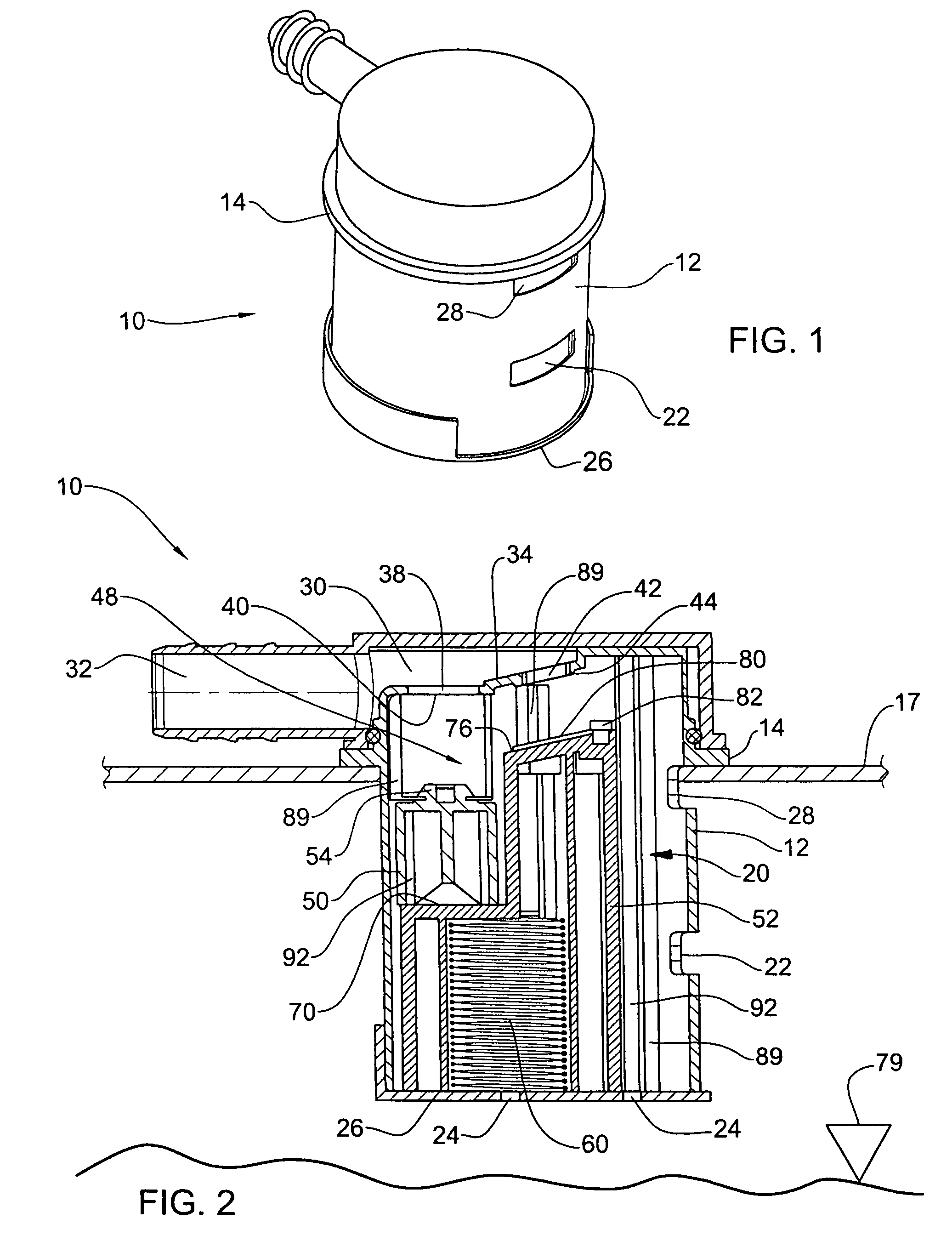
[0053]Attention is first directed to FIGS. 1 and 2 for understanding the construction of a valve according to the present invention, generally designated 10. The valve comprises a cylindric housing portion 12 formed with a flange 14 at an upper portion thereof for attachment, by heat welding or other means as known in the art, to an upper wall portion 17 of a fuel tank (not shown), where a major portion of the housing 12 extends into the fuel tank. As will be discussed hereinafter in connection with the embodiment of FIG. 6, there is illustrated a valve formed with a different arrangement for attachment to the fuel tank.

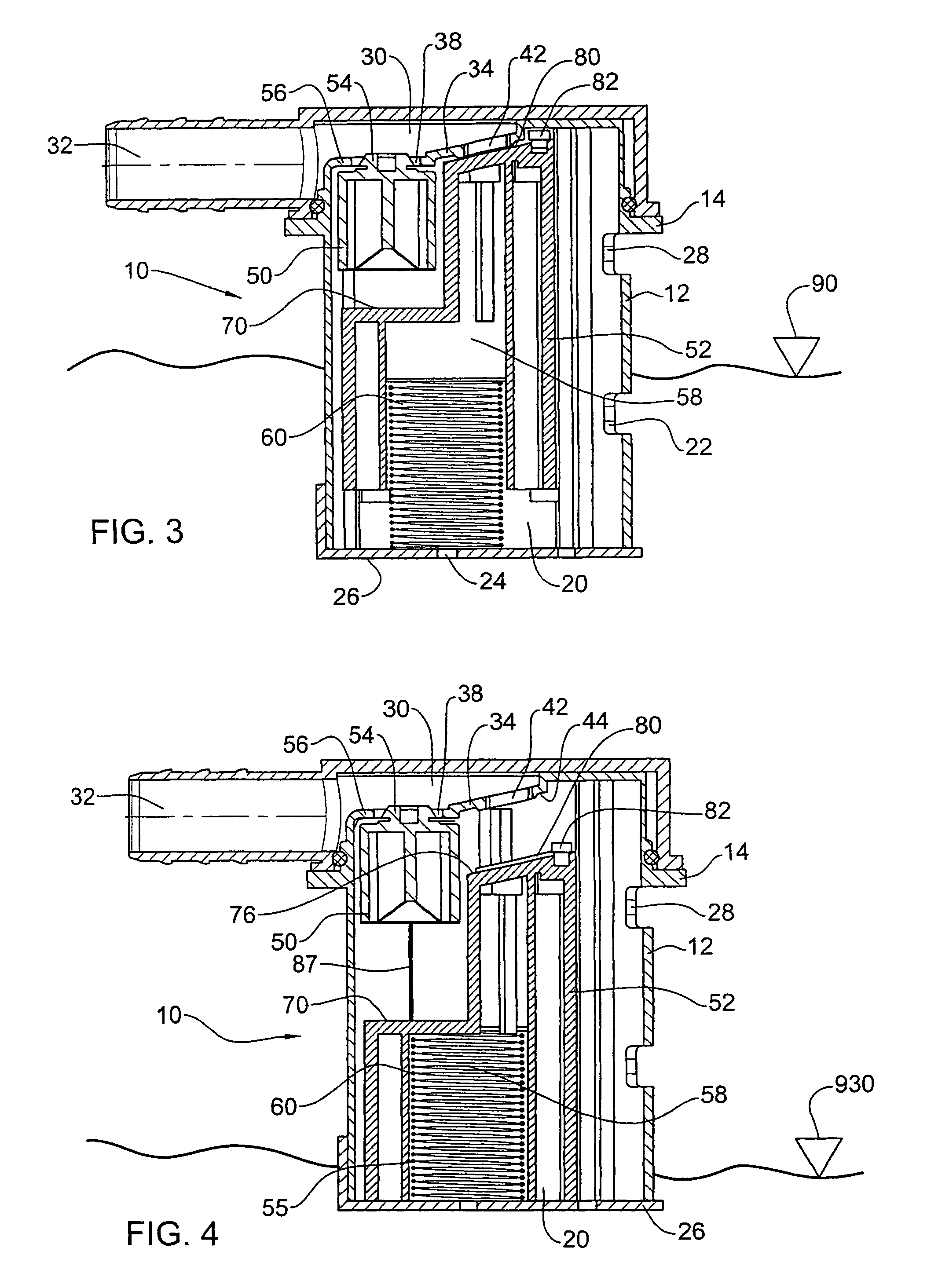
[0054]As can further be seen in FIGS. 2 to 4, the housing 12 defines a confined space 20, a lower fluid inlet 22, several fluid inlets 24 at a bottom wall 26 of the housing, and at a top end of the confined space, an upper inlet port 28.

[0055]The valve 10 is formed at an upper portion thereof with a fluid outlet chamber 30 being in flow communication with an outlet d...

second embodiment

[0073]Further attention is now made to FIGS. 7 to 13, directed to a valve in accordance with the present invention generally designated 130. The valve is of the type comprising an outlet duct 136 connected to a fuel vapor treating device, e.g. canister 138 via suitable tubing 140, and further comprising a venting port 146 being in flow communication with a filler neck 148 of a fuel tank 150 via a suitable piping 154

[0074]For the sake of convenience, elements in the valve which are similar to elements disclosed in connection with the previous embodiment of FIGS. 1 to 5 are designated with the same reference numbers shifted by 200.

[0075]The valve 130 similar to the previous embodiment comprises a cylindric housing 212 fitted with a first stage float member 250 and the second stage float member 252 substantially of the same structure as defined in connection with the first embodiment. An anti-splash skirt 302 is articulated to the housing 212 in the same fashion as disclosed in connect...


PUM


Abstract

A valve comprising a housing accommodating a first and a second outlet port, a first stage float member associated with the first outlet port and a second stage float member associated with the second outlet port. The float members are displaceable within the housing about parallel axes, between an open position and a closed position. The first stage float member at least partially overlaps over the second stage float member.

Description

FIELD OF THE INVENTION[0001]The present invention is generally in the field of fuel tank valves and in particular, it is concerned with a dual float valve for use in vehicle fuel tanks having multi purpose functions.BACKGROUND OF THE INVENTION[0002]A large variety of valves for use with vehicles' fuel tanks are known, among which are of more relevance with respect to the present invention those fitted with two or more valve assemblies.[0003]For example, U.S. Pat. No. 6,675,779 discloses a tank venting apparatus or a fill-limit and tank ventilation valve is disclosed for use with a fuel tank. The valve has a housing which contains a first valve assembly, second valve assembly, third valve assembly and fourth valve assembly. The first valve assembly primarily communicates with the fuel tank. The fourth valve assembly communicates with a vapor recover canister and a filler neck to the tank. The first valve assembly also communicates with the third valve assembly and the second valve as...

Claims


Application Information

Patent Timeline
Patent Type & Authority Patents(United States)
IPC IPC(8): F16K24/04B60K15/035
CPCF16K17/36F16K24/042B60K15/03519B60K2015/03576Y10T137/0777Y10T137/3099Y10T137/0874F16K24/04B60K15/035B60K11/04F02M37/00
Inventor OLSHANETSKY, VLADIMIRVULKAN, OMERKASPI, YARONAKIAN, ILAN
Owner RAVAL - AGRI COOP SOCIETIES
Why Eureka
Try Eureka