
Plug connector

a plug connector and connector technology, applied in the direction of electrical apparatus, connection, coupling device connection, etc., can solve the problems of easy deformation of the fastening element, and difficulty in increasing the distance between the push head and the push head, so as to achieve convenient disengagement of the plug connector and connection. , the effect of firm connection

Inactive Publication Date: 2007-04-24
ALL BEST ELECTRONICS
View PDF6 Cites 36 Cited by
  • Summary
  • Abstract
  • Description
  • Claims
  • Application Information

AI Technical Summary

Benefits of technology

"The present invention provides a plug connector with a fastening structure that allows for easy connection and disengagement with a receptacle. The plug connector includes a main body with a middle slide way and a recess for receiving an elastic element, an elastic plate with hooks for engagement with the receptacle, and a pull member with a forward projected section and a stopper that presses against the elastic element. The pull member is pulled rearward to disengage the plug connector from the receptacle. The technical effects of the invention include convenient and easy use of the plug connector and improved manipulation of the fastening structure."

Problems solved by technology

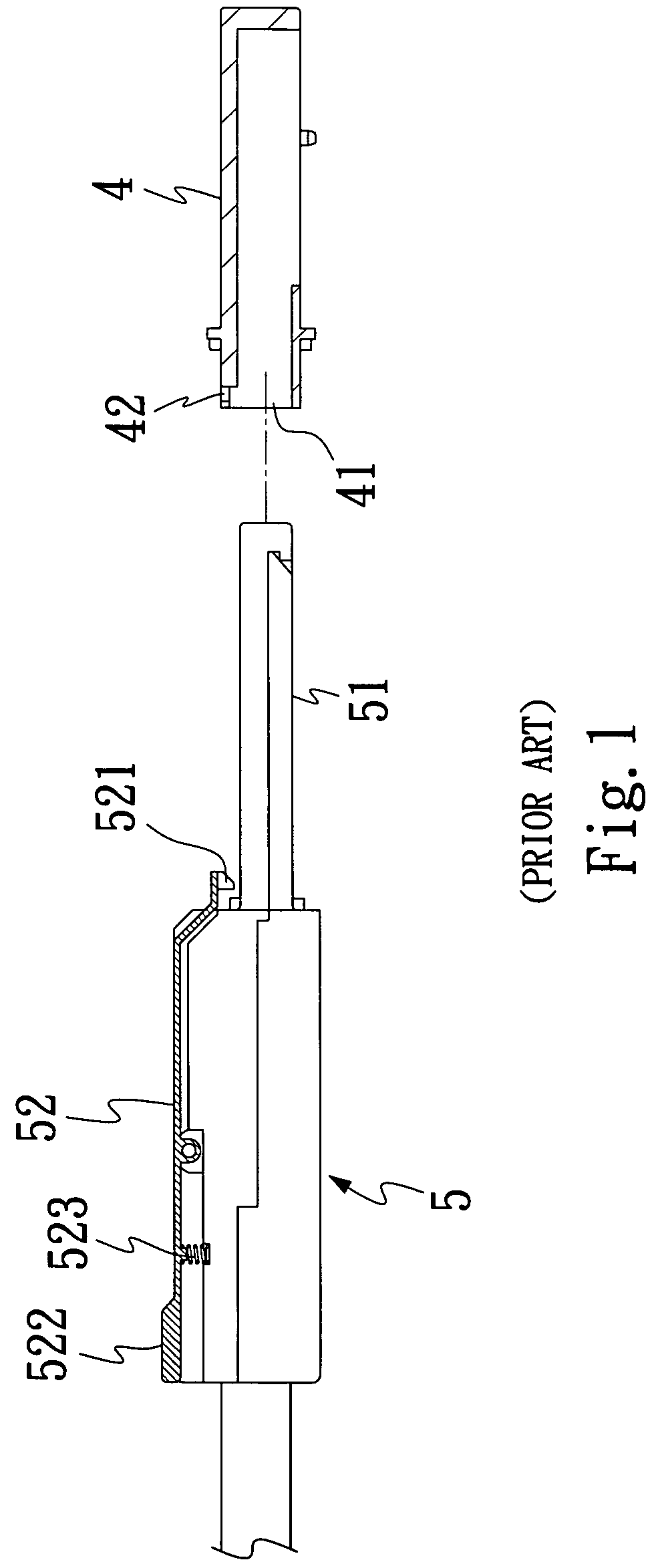
However, as a result of the miniaturization of electronic products, it is not easy to increase the distance between the push head 522 and the main body 5.2. To meet the requirement of miniaturized electronic products, the fastening element 52 must have a minimized thickness, which inevitably reduces the structural strength of the fastening element 52 to result in easy deformation of the fastening element 52.

Method used


Image

  • Plug connector
  • Plug connector
  • Plug connector

Examples


Embodiment Construction

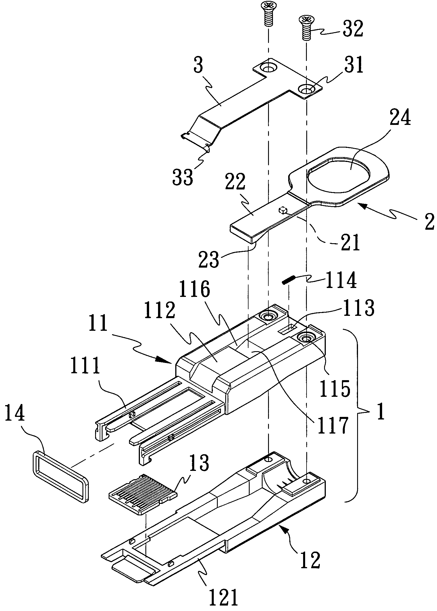
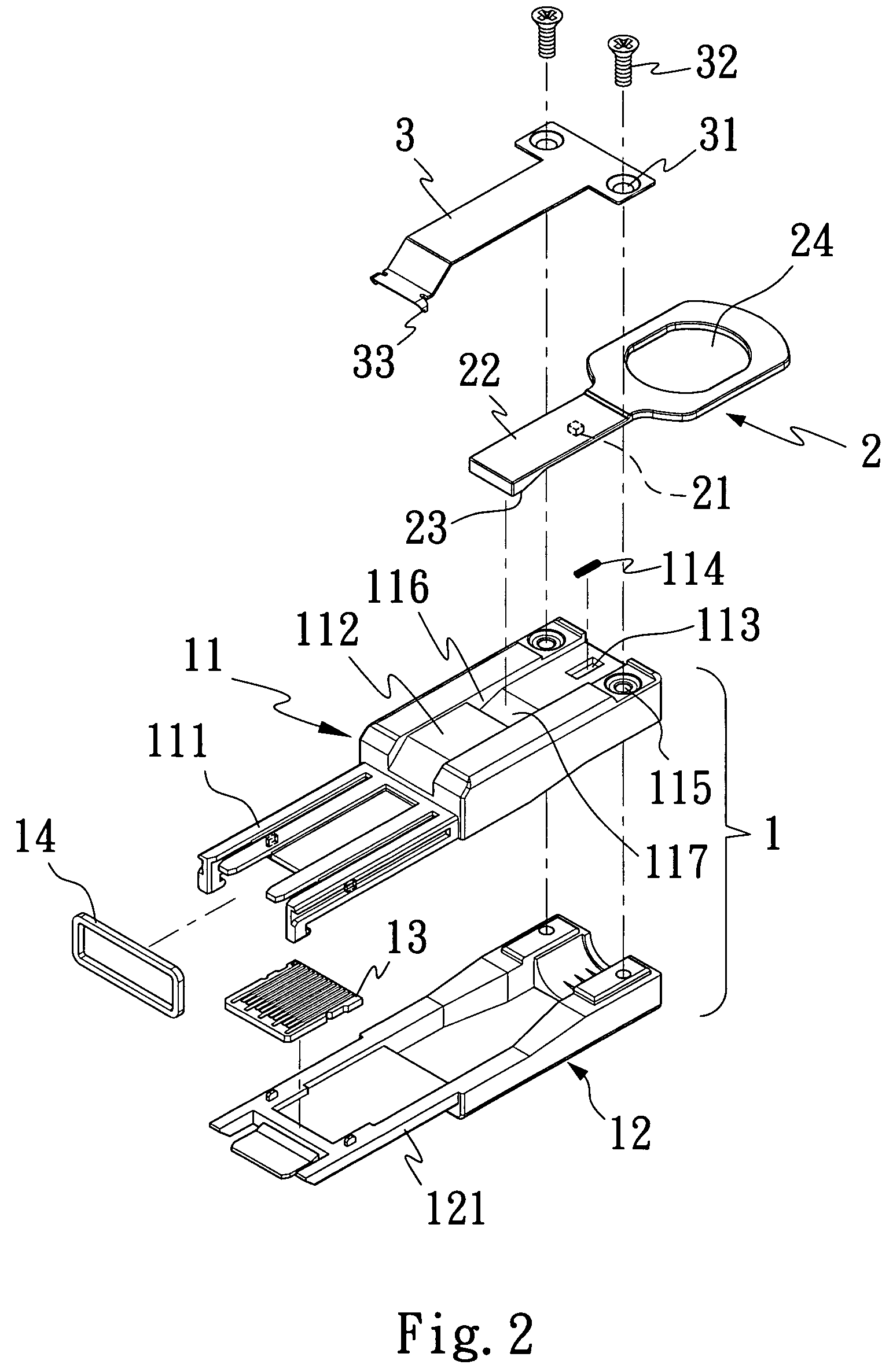
[0018]Please refer to FIGS. 2 and 3 that are exploded and assembled perspective views, respectively, of a plug connector according to a preferred embodiment of the present invention. As shown, the plug connector according to the present invention includes a main body 1, a pull member 2, and an elastic plate 3.

[0019]The main body 1 is formed from an upper case 11 and a lower case 12 closed to each other. An upper and a lower plug head 111, 121 are horizontally forward extended from a front end of the upper and the lower case 11, 12, respectively, for extending into a plug hole 41 on a receptacle 4 corresponding to the plug connector. A conductive rubber ring 14 is mounted around a base of the upper and the lower plug head 111, 121; and a circuit board 13 having signal wires connected thereto is mounted between the upper and the lower plug head 111, 121, as shown in FIGS. 3, 4, and 5.

[0020]The upper case 11 of the main body 1 is provided at a top surface with an axially extended middl...


PUM


Abstract

A plug connector includes a main body having a forward plug head for plugging in a corresponding receptacle, and an axial middle slide way having a lowered section formed on a top surface; an elastic plate fixed to a rear end of the main body with two hooks formed at a front free end for engaging with two engaging holes on the receptacle; and a pull member having a forward projected section movably located in the middle slide way below the elastic plate. When the pull member is pulled rearward, a downward protruded front end of the forward projected section slides out of the lowered section onto the middle slide way to raise a middle section of the elastic plate, so that the hooks of the elastic plate disengage from the receptacle, allowing the plug head of the main body to unplug from the receptacle.

Description

FIELD OF THE INVENTION[0001]The present invention relates to a plug connector, and more particularly to a plug connector having a fastening structure that secures the plug connector to a receptacle and could be easily operated to allow convenient unplugging of the plug connector from the receptacle.BACKGROUND OF THE INVENTION[0002]FIG. 1 shows the conventional fastening structure provided on a plug connector and a corresponding receptacle. As shown, a main body 5 of the conventional plug connector includes a forward projected plug head 51 for plugging in a plug hole 41 on the receptacle 4, so that a closed circuit is formed to allow signal transmission. A fastening element 52 is movably connected to a top of the main body 5. A rear end of the fastening element 52 has a push head 522. A spring 523 is mounted between the push head 522 and the main body 5. At least one hook 521 is provided at a front end of the fastening element 52 for engaging with a locating hole 42 correspondingly f...

Claims


Application Information

Patent Timeline
Patent Type & Authority Patents(United States)
IPC IPC(8): H01R13/627
CPCH01R13/6275H01R13/6658
Inventor YANG, HAVEN
Owner ALL BEST ELECTRONICS
Learn More