Adapter with a base housing for a bus bar system having a number of bus bars

Inactive Publication Date: 2000-09-05
RITTALWERK RUDOLF LOH GMBH & CO KG
View PDF4 Cites 11 Cited by
  • Summary
  • Abstract
  • Description
  • Claims
  • Application Information

AI Technical Summary

Problems solved by technology

With known adapters of this type, the mounting of the connecting contacts in the base housing provides considerable difficulties in assuring: 1) a definite electrical connection b

Method used


Image

  • Adapter with a base housing for a bus bar system having a number of bus bars
  • Adapter with a base housing for a bus bar system having a number of bus bars
  • Adapter with a base housing for a bus bar system having a number of bus bars

Examples


Embodiment Construction

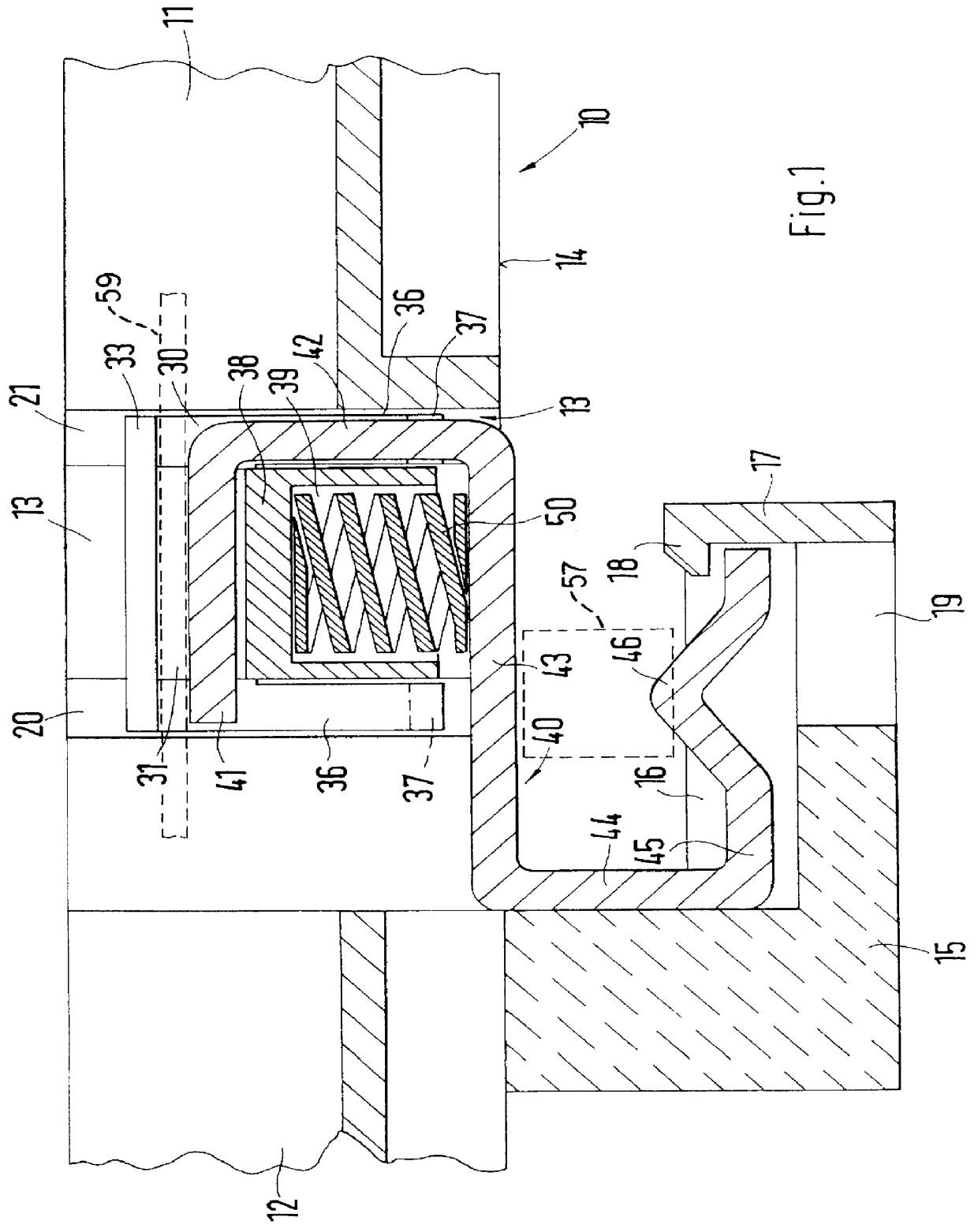
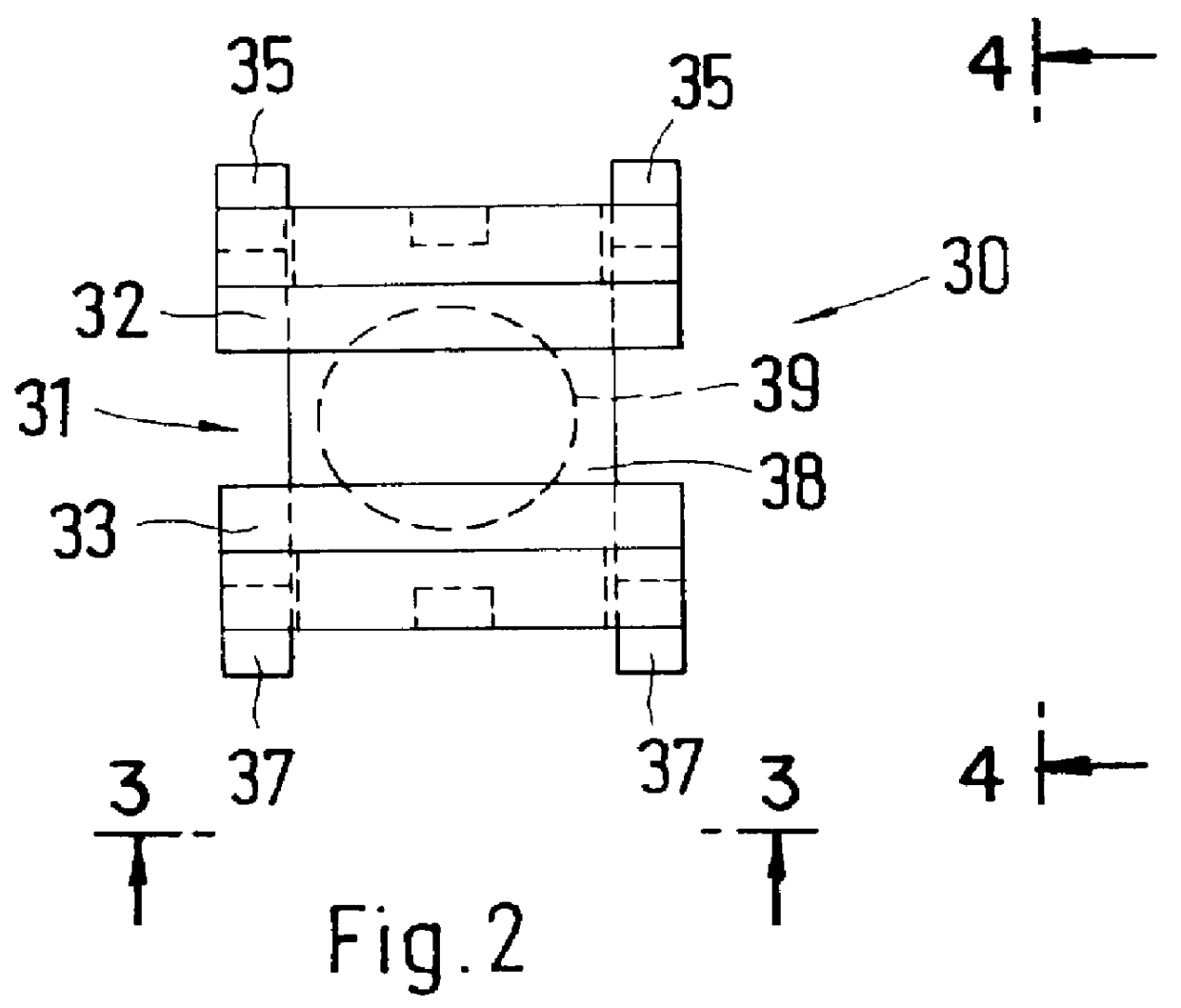
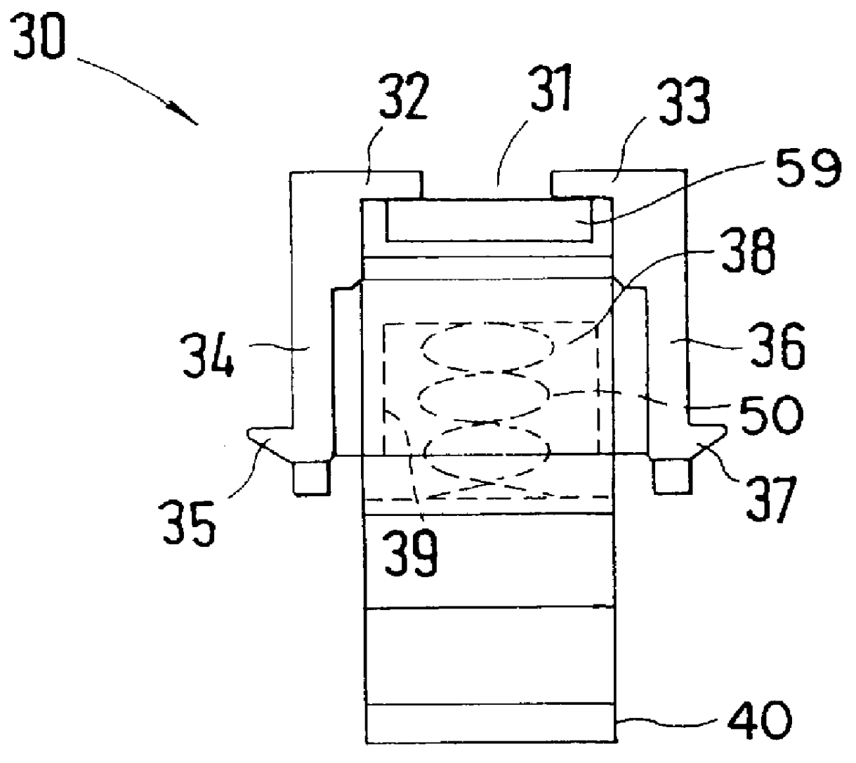
The basic structure of the base housing 10 is determined by the number and spacing of the bus bars in the bus bar system. Respectively longitudinally oriented contact rail receptacles are formed in the top of the base housing 10 which, as shown in FIG. 1, terminate with the sections 11 and 12 in a snap-in receiver void 13 in the area of the formed-on suspension hooks 15 of the base housing 10. On its sides aligned parallel with the contact rail receptacles 11, 12, this snap-in receiver void 13 has formed-in, vertical guide grooves 20 and 21 for pairs of snap-in springs 34 and 36 with outward oriented snap-in shoulders 35 and 37 formed on a contact support 30 in accordance with FIGS. 2 to 4. The walls of the snap-in receiver voids 13 with the guide grooves 20 and 21 support snap-in receptacles, into which the snap-on shoulders 35 and 37 are snapped, but which permit a limited vertical displacement of the contact support 30 in the snap-in receiver void 13. The snap-in shoulders 35 and...


PUM


Abstract

An adapter for a base housing to which suspension hooks are attached, is accessible for the insertion of connecting contacts to connect contact rails with bus bars. A pre-assembled unit including the contact support, a spring element and a connecting contact is snapped into a snap-in receiver void of the base housing in the area of the base housing suspension hook and makes definite connections between the bus bar, the connecting contact and the contact rail.

Description

1. Field of the InventionThis invention relates to an adapter for a base housing to which suspension hooks have been attached. These adapters will correspond to the number of bus bars of a bus bar system and are offset with respect to each other in a longitudinal direction of the base housing in a manner corresponding to a distance between the bus bars. The adapters are accessible for the insertion of connecting contact rails inserted through contact rail receptacles formed into a top of the base housing. The adapters are oriented in the longitudinal direction and connect the contact rails with the bus bars.2. Description of Prior ArtWith known adapters of this type, the mounting of the connecting contacts in the base housing provides considerable difficulties in assuring: 1) a definite electrical connection between the contact rail and the connecting contacts, and 2) after the adapter has been suspended, the connecting contact provides a definite electrical connection with the bus ...

Claims


Application Information

Patent Timeline
IPC IPC(8): H02B1/20
CPCH02B1/205
Inventor WAGENER, HANS
Owner RITTALWERK RUDOLF LOH GMBH & CO KG
Why Eureka
Try Eureka