Wind turbine blade with submerged boundary layer control means

Inactive Publication Date: 2010-08-19
LM GLASSFIBER
View PDF14 Cites 10 Cited by
  • Summary
  • Abstract
  • Description
  • Claims
  • Application Information

AI Technical Summary

Benefits of technology

[0024]The chordwise position of the boundary layer control means can be between 10% and 80% of the chord as seen from the leading edge. Alternatively, they are positioned within a region extending between 20% and 70% of the chord as seen from the leading edge

Problems solved by technology

This in turn results in forces, which tend to retard the boundary layer, which can be strong enough to arrest or reverse the flow, which can cause the fluid to separate and behave in a non-predictable manner.
This causes an increase in drag due to the cross-sectional area of separated flow in the wake of the flow control medium, which in turn reduces the lift of the wind turbine

Method used


Image

  • Wind turbine blade with submerged boundary layer control means
  • Wind turbine blade with submerged boundary layer control means
  • Wind turbine blade with submerged boundary layer control means

Examples


first embodiment

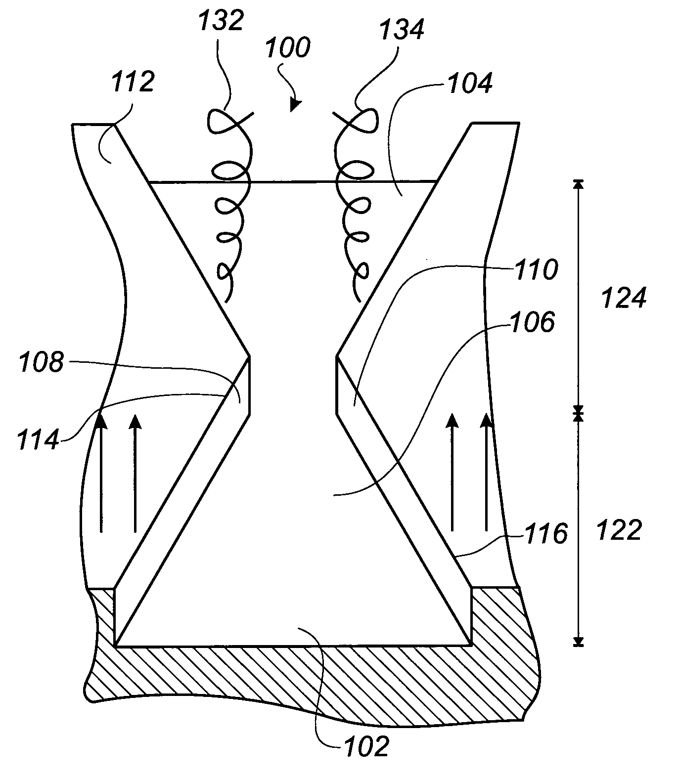
[0049]FIG. 3 shows a schematic view of a boundary layer control means 100 for maintaining flow of a flowing medium attached to the exterior of a flow control member, such as a wind turbine blade, having a flow control surface 112. The boundary layer control means 100 comprises a channel, which is submerged in the flow control surface 112. The channel extends in the direction of a free flow having a flow direction, which is depicted with arrows in the figure. The channel comprises a first end 102 facing the free flow and a second end 104 positioned downstream in the flow of the flowing medium from the first end 102.

[0050]The channel comprises a bottom surface 106 extending from the first end 102 to the second end 104. The channel further comprises a first sidewall 108 extending between the flow control surface 112 and the bottom surface 106, as well as a second sidewall 110 extending between the flow control surface 112 and the bottom surface 106. The first sidewall 108 forms a first...

fourth embodiment

[0058]FIG. 8 shows a boundary layer control means for maintaining a flow attached to the exterior of a flow control member and is a variation of the embodiment shown in FIG. 3. The boundary layer control means comprises a channel submerged in a flow control surface 412 and has a first end 402 and a second end 404.

[0059]The sides of the channel are defined by a first sidewall 408 and a second sidewall 410, which have a first height and a second height, respectively. The first sidewall 408 and the second sidewall 410 have a maximum height between the first flow accelerating zone and the second channel zone. The first height and the second height are decreasing from this position of maximum height towards the first end 402 and the second end 404, so that the channel emerges at the flow control surface 412 at the first end 402 and the second end 404.

[0060]FIG. 9 shows a fifth embodiment of a boundary layer control means, wherein like numerals refer to like parts of the fourth embodiment...


PUM


Abstract

A wind turbine blade having a longitudinal direction with a root end and a tip end as well as a chord extending in a transverse direction between a leading edge and a trailing edge is described. The blade comprises a flow control surface with a suction side and a pressure side. A number of boundary layer control means is formed in the flow control surface. The boundary layer control means include a channel submerged in the flow control surface with a first end facing towards the leading edge and a second end facing towards the trailing edge of the blade. The channel comprises: a bottom surface extending from the first end to the second end, a first sidewall extending between the flow control surface and the bottom surface and extending between the first end and the second end, the first sidewall forming a first sidewall edge between the first side wall and the flow control surface, and a second sidewall extending between the flow control surface and the bottom surface and extending between the first end and the second end, the second sidewall forming a second sidewall edge between the second side wall and the flow control surface. The channel at the first end comprises a first flow accelerating channel zone adapted for accelerating a flow, and at the second end comprises a second channel zone, where the first sidewall and the second sidewall are diverging towards the trailing edge of the blade.

Description

TECHNICAL FIELD[0001]The present invention relates to a wind turbine blade having a longitudinal direction with a root end and a tip end as well as a chord extending in a transverse direction between a leading edge and a trailing edge, the blade comprising a flow control surface with a suction side and a pressure side.BACKGROUND[0002]There are many situations, where it is desirable to provide a method of delaying or preventing flow separation between a flowing medium and a flow control surface in regions where the boundary layer of the flow medium due to the profile of the flow control surface is subjected to pressure gradients, which are sufficient to cause flow separation.[0003]When a viscous fluid passes over a wind turbine blade towards the trailing edge, the fluid flows from a region with low static pressure to a region with high static pressure, in the process being subjected to an adverse pressure gradient. This in turn results in forces, which tend to retard the boundary lay...

Claims


Application Information

Patent Timeline
IPC IPC(8): F03D1/06F03D7/02
CPCF01D5/145F03D1/0675F05B2240/122F05B2240/30B64C2230/28Y02T50/166F05D2240/30F05D2240/127B64C2230/26Y02E10/721Y02E10/72Y02T50/10Y02T50/60F05B2240/3062
Inventor FUGLSANG, PETERBOVE, STEFANO
Owner LM GLASSFIBER
Why Eureka
Try Eureka