Heat sink assembly having a clip

a technology of heat sink and clip, which is applied in the direction of lighting and heating apparatus, electrical apparatus casings/cabinets/drawers, instruments, etc., can solve the problems of inability to accurately adjust the length of the locking arms of the clip is either too short to become difficult to engage with the clasp on the printed circuit board, and the length of the locking arms is too short to achieve the effect of accurate and easy engagement and easy disengagement of the clip

Inactive Publication Date: 2010-01-07
FU ZHUN PRECISION IND SHENZHEN +1
View PDF8 Cites 11 Cited by
  • Summary
  • Abstract
  • Description
  • Claims
  • Application Information

AI Technical Summary

Benefits of technology

[0008]A heat sink assembly includes a heat sink and a clip assembly. The clip assembly includes a clip and a pair of movable fasteners pivotally connected to two opposite ends of the clip. The clip includes a main body, two pressing portions extending outwardly from two opposite ends of the main body and two locking arms extending oppositely from the two pressing portions, respectively. The movable fasteners each includes a main body, a pair of receiving portions curved upwardly from the main body and receiving a corresponding locking arm therein and a hook extending downwardly from the main body and engaging with a clasp on a printed circuit board. By the pivotably movable fasteners the clip assembly can accurately and easily engage with the clasps to enable the pressing portions to exert sufficient pressing force on the heat sink so that the heat sink can have an intimate contact with an electronic component on the printed circuit. Furthermore, by the pivotably movable fasteners, the disengagement of the clip assembly from the printed circuit board can also be easily achieved.

Problems solved by technology

However, in operation, the locking arms of the clip usually fail to have an appropriate length for properly engaging with the clasps formed on the printed circuit board, whereby the pressing portion cannot firmly press the heat sink toward the printed circuit board to enable the heat sink to have an intimate contact with the CPU.
The length of the locking arms of the clip is either too long to easily disengage from the clasps on the printed circuit board when the clip is suffered vibration, or too short to become difficult to engage with the clasps on the printed circuit board.

Method used


Image

  • Heat sink assembly having a clip
  • Heat sink assembly having a clip
  • Heat sink assembly having a clip

Examples


Embodiment Construction

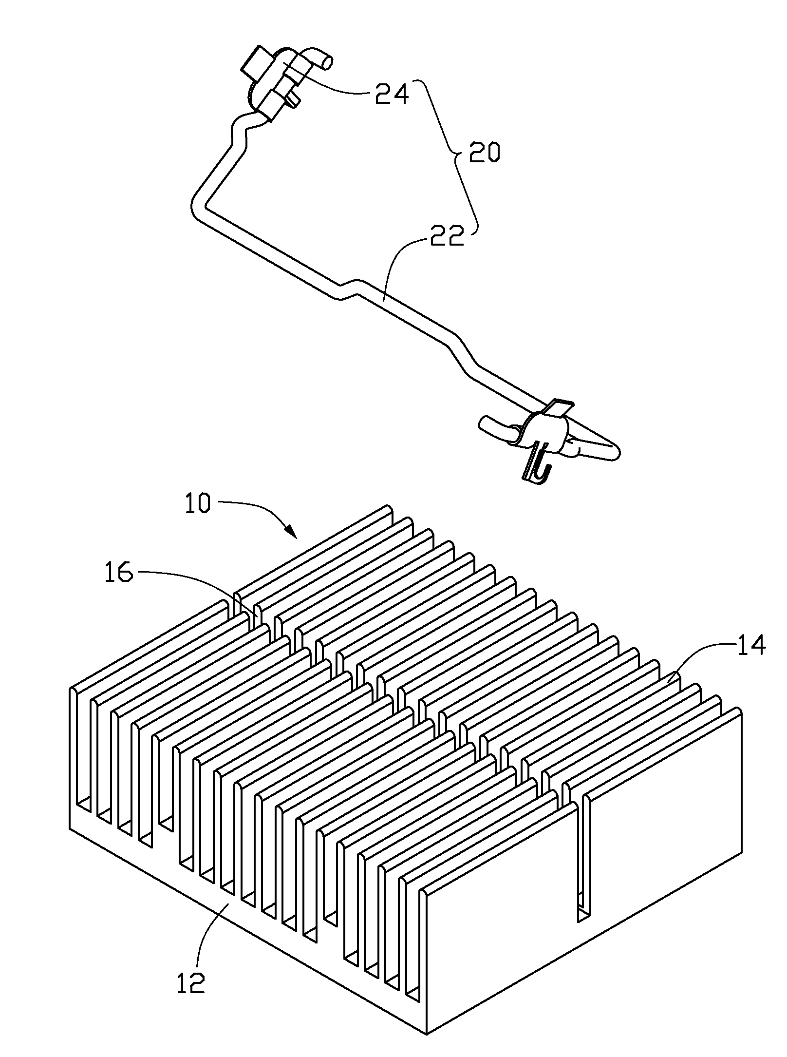
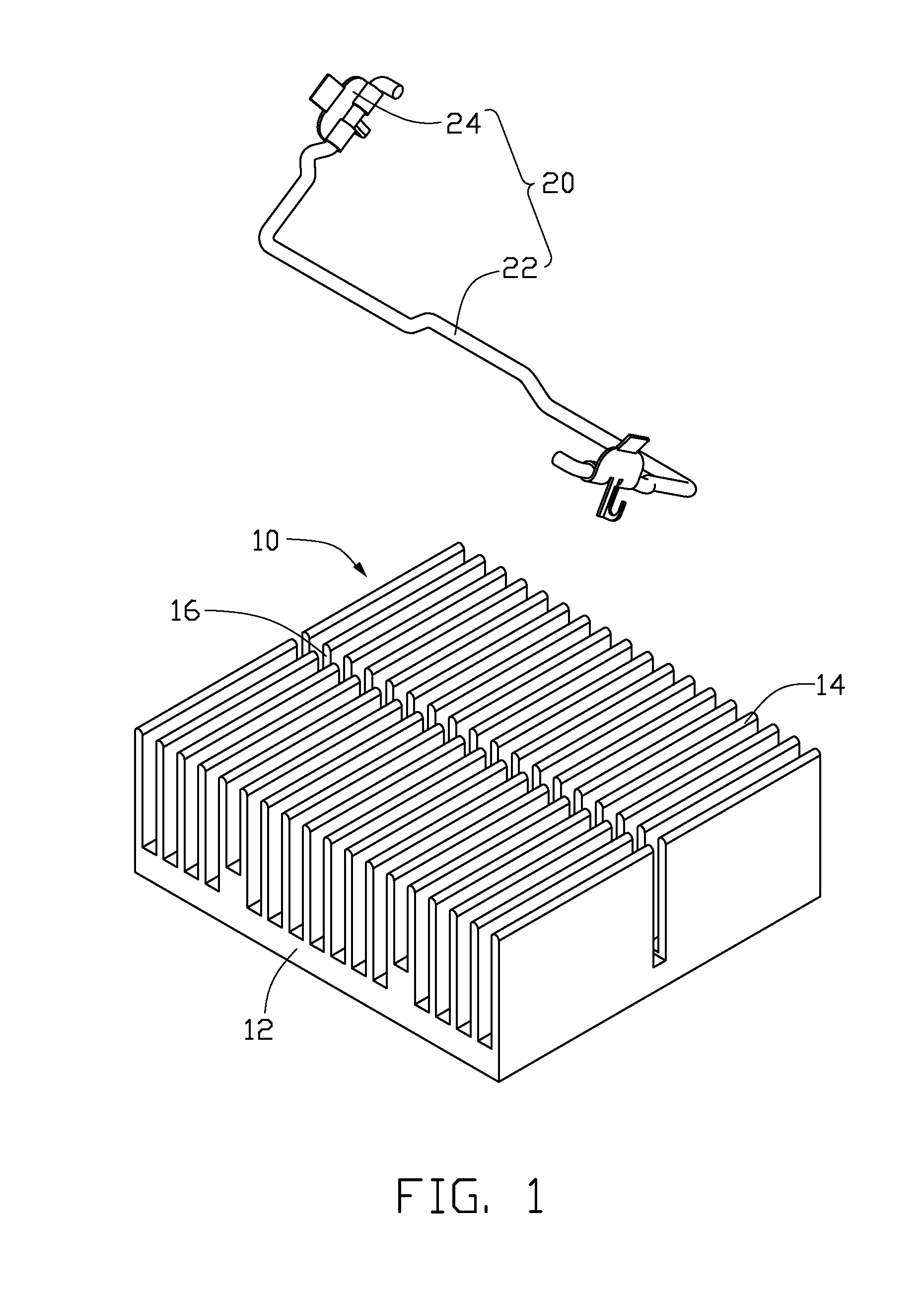
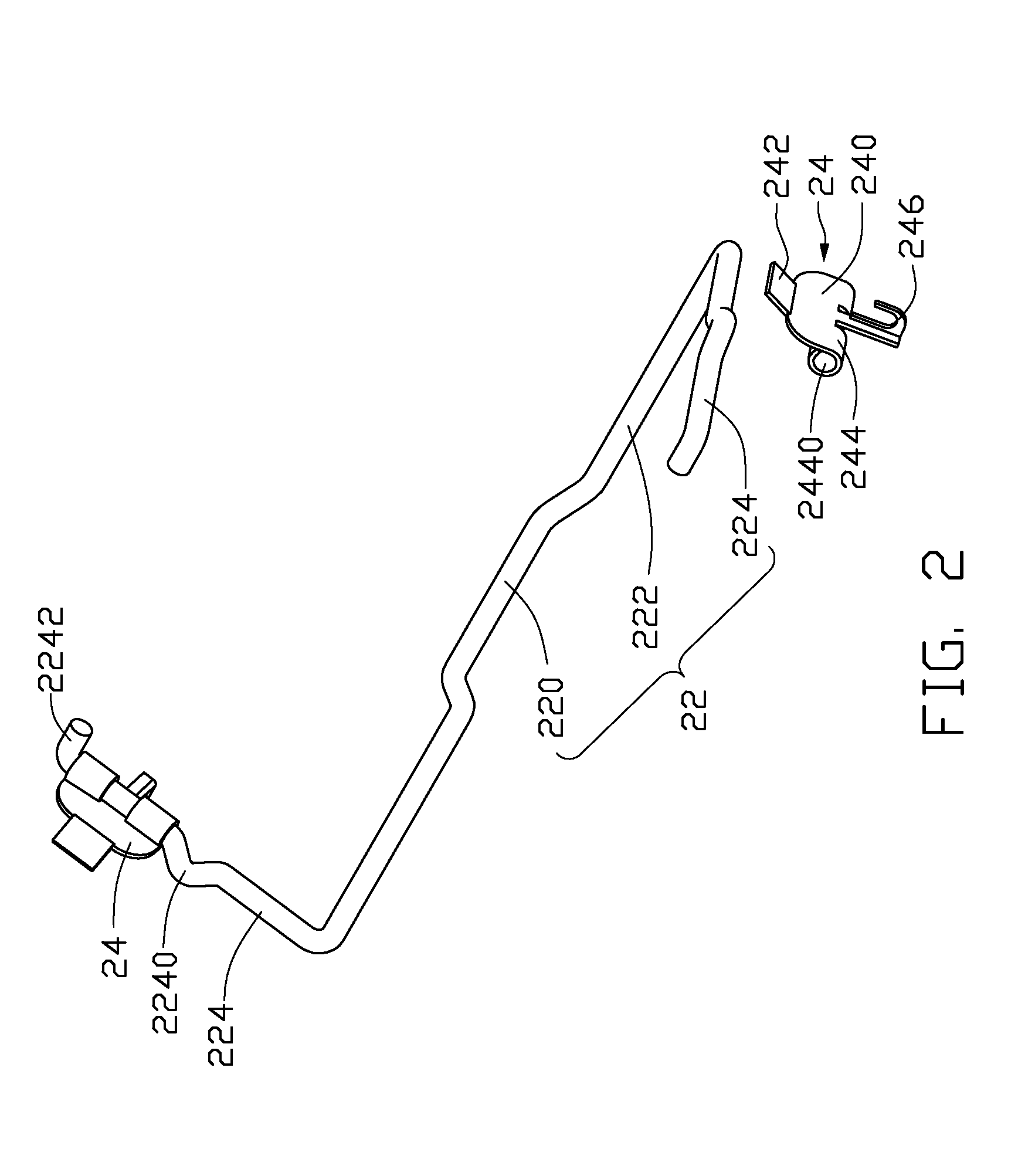
[0015]Referring to FIGS. 1-4, a heat sink assembly, which is used for dissipating heat generated from an electronic element (not shown) on a printed circuit board 100, comprises a heat sink 10 and a clip assembly 20. The clip assembly 20 is used to engage with clasps 120 (only one shown) formed on the printed circuit board 100 and located near two diagonally opposite corners of the heat sink 10 to secure the heat sink 10 onto the printed circuit board 100, whereby the heat sink 10 can have an intimate contact with the electronic element. In the preferred embodiment, the electronic element is a CPU or a chip set.

[0016]The heat sink 10 is integrally made of metal with a high heat conductivity such as copper, aluminum or an alloy thereof. The heat sink 10 comprises a rectangular base 12 and a plurality of fins 14 extending upwardly from a top surface of the base 12. The fins 14 are parallel to each other. A channel (not labeled) is defined between every two adjacent fins 14. A straight...


PUM


Abstract

A heat sink assembly includes a heat sink and a clip assembly. The clip assembly includes a clip and a pair of movable fasteners pivotally connected to the clip. The clip includes a main body, two pressing portions extending from two opposite ends of the main body and two locking arms extending oppositely from the two pressing portions, respectively. The movable fasteners each include a main body, a pair of receiving portions curved upwardly from the main body and receiving a corresponding locking arm therein and a hook extending downwardly from the main body and engaging with a clasp on a printed circuit board. A distance from each of the hooks of the movable fasteners to a corresponding clasp can be adjustable via rotation of the movable fasteners around the locking arms of the clip.

Description

BACKGROUND OF THE INVENTION [0001]1. Field of the Invention[0002]The present invention relates to a heat sink assembly, and more particularly to a heat sink assembly having a clip which can firmly secure a heat sink to a heat-generating component such as a central processing unit (CPU) mounted on a printed circuit board.[0003]2. Description of Related Art[0004]It is widely acknowledged that heat is produced during operations of electronic devices such as central processing units (CPUs). The produced heat must be quickly removed to ensure the CPUs working normally. Typically, a heat sink is disposed on the CPU mounted on the printed circuit board to dissipate the heat therefrom.[0005]Typically, linear-type clips were widely used for securing of heat sinks. A linear-type clip, which is integrally made from a resilient metal wire, generally includes an elongated central pressing portion and a pair of locking arms extending from opposite ends of the elongated central pressing portion in...

Claims


Application Information

Patent Timeline
Patent Type & Authority Applications(United States)
IPC IPC(8): H05K7/20
CPCH01L23/4093H01L2924/0002Y10T24/44017H01L2924/00
Inventor HE, XIANG-YANGZHANG, JING
Owner FU ZHUN PRECISION IND SHENZHEN
Why Eureka
Try Eureka