Inkjet printing and method

a technology of inkjet printing and printing method, applied in the field of inkjet printing, can solve the problems of not being able to easily and practicalally upgrade existing printers to utilize the new technology, and achieve the effect of reducing or eliminating the conventional problems relating to inkjet printing, and being easy to change in and out of the printer

Inactive Publication Date: 2004-04-01
HEWLETT PACKARD DEV CO LP
View PDF3 Cites 9 Cited by
  • Summary
  • Abstract
  • Description
  • Claims
  • Application Information

AI Technical Summary

Benefits of technology

0012] Accordingly, in view of the above, it is seen that the present invention makes it possible to diminish or eliminate the conventional problems relating to printer and printhead upgrades by providing a method and apparatus by which a printer may be altered in an economical fashion to adapt to, communicate with, and utilize any new applicable printhead. A new printhead controller circuit (i.e., and ASIC chip or chipset) may be inserted into the printer, and the new printhead will then be controlled by the print formatter circuit via this new printhead controller.
0013] The present invention provides a method and apparatus for providing communication between the formatter of a printer and a printhead; which will allow for the adaptation of multiple printhead types with little alteration of the printer hardware. This new printer communication interface or protocol will function with an application specific integrated circuit chip (i.e., an ASIC) which is easily changed in and out of the printer.

Problems solved by technology

A long-standing challenge and deficiency in the manufacturing of such conventional inkjet printers 500 has been that when new improved printheads are developed and come on the market there is no easy or practical way to upgrade existing printers to utilize the new technology.
As new printhead technology and new printheads become available, they require control signals that the print formatter and printhead controller circuit 502 cannot provide.

Method used


Image

  • Inkjet printing and method
  • Inkjet printing and method
  • Inkjet printing and method

Examples


Embodiment Construction

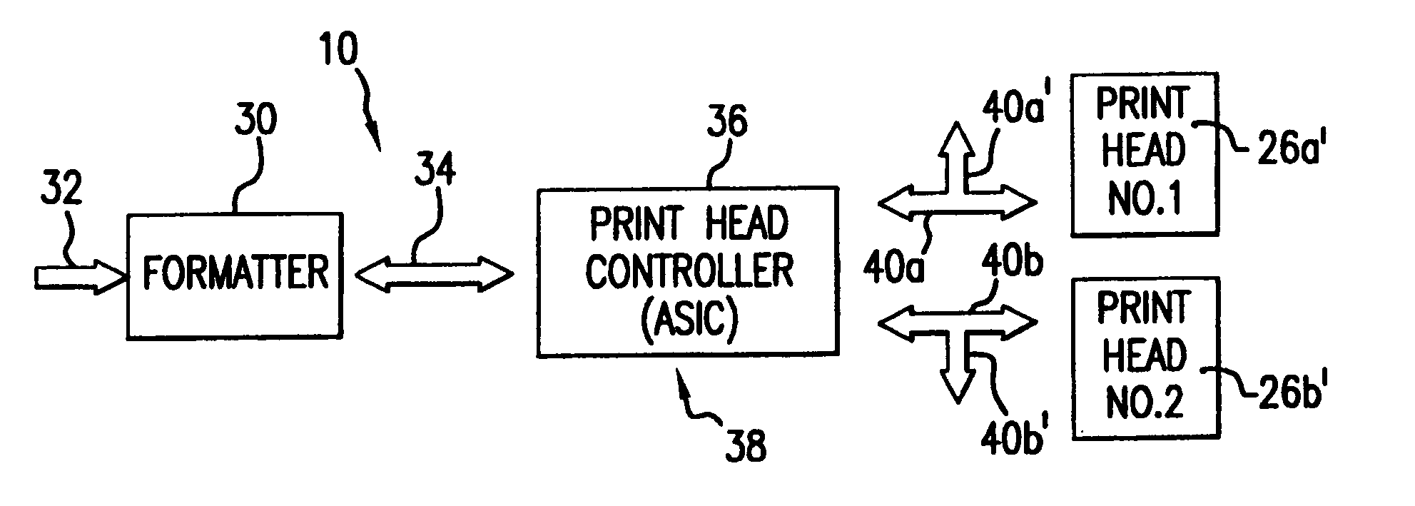
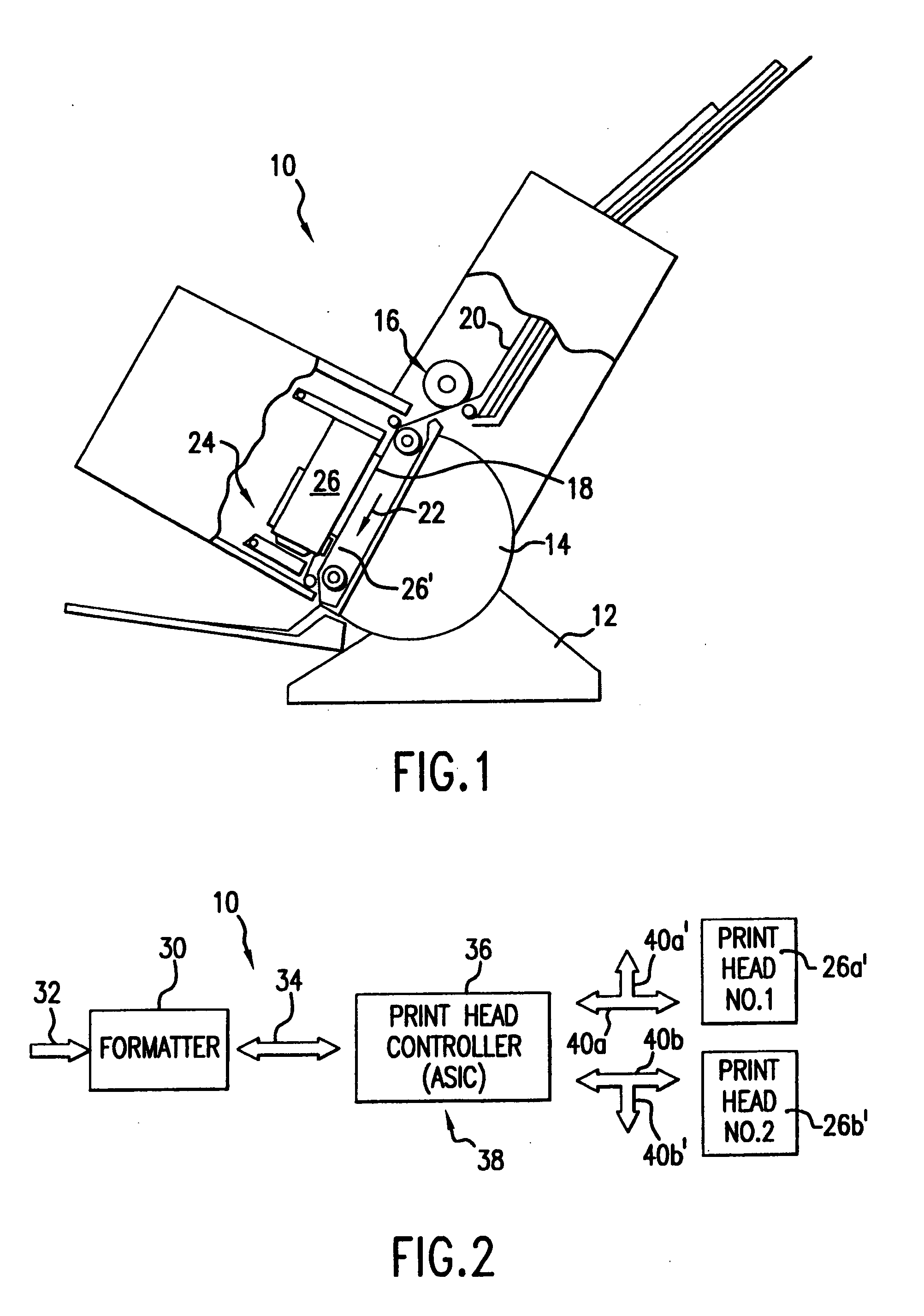
[0035] FIG. 1 shows an exemplary inkjet printer 10. This printer 10 includes a base 12 carrying a housing 14. Within the housing 14 is a feed mechanism 16 for controllably moving a print medium (i.e., paper this case, although the invention is not so limited) through the printer 10. Those ordinarily skilled in the pertinent arts will understand that the feed mechanism 16 may be configured to feed sheet paper or medium, or may be configured to feed fan-fold, or roll paper or medium, or may be configured to feed print medium of another shape or style. In this exemplary printer 10, the feed mechanism 16 controllably moves a single sheet of paper 18 from a paper magazine 20 along a print path 22 within the printer 10. The printer 10 includes a traverse mechanism 24 (i.e., a carriage) carrying an inkjet print cartridge 26. The traverse mechanism moves the inkjet printing cartridge 26 perpendicularly to the direction of movement of the paper 18 (i.e., the cartridge 26 is moved perpendicul...


PUM


Abstract

An inkjet printer includes a print formatter circuit which receives high-level printing signals from a host computer, such as a PC or mainframe computer. The print formatter circuit translates the high level printing signals into signals of an intermediate-level interface language, which is communicated to a printhead controller circuit. The printhead controller circuit in turn translates the intermediate-level interface language signals into discreet-event commands, and other finite action-element or condition-element signals or requirements, that are communicated to the inkjet printer and to a printhead in the printer. The discreet-event commands, finite action-element, and finite condition-element signals effect control of the movements of a carriage of the printer, or print medium movable past the carriage, and the actions of an inkjet printing cartridge carried in the carriage such that ink or other printing fluid is controllably ejected from the printing cartridge onto the print medium to form images or characters.

Description

[0001] 1. Field of the Invention[0002] This invention relates generally to inkjet printing. More particularly, this invention relates to a method used to control one or more printheads in an inkjet printer, and to an inkjet printer utilizing this method.[0003] 2. Related Technology[0004] Inkjet printers or plotters typically have a print cartridge mounted on a carriage. This carriage is traversed back and forth across the width of a print medium (i.e., usually paper or a plastic plotting film, for example) as the print medium is fed through the printer or plotter. Plural orifices on the print cartridge are fed ink (or other printing fluid) by one or more channels communicating from a reservoir of the print cartridge. Energy applied individually to addressable resistors (or other energy-dissipating elements, for example, to piezoelectric actuators), transfers energy to printing fluid; which is within or associated with selected ones of the plural orifices. These orifices then eject p...

Claims


Application Information

Patent Timeline
Patent Type & Authority Applications(United States)
IPC IPC(8): B41J2/05G06K15/10B41J2/01
CPCB41J2/04563G06K15/102B41J2/04586
Inventor VIVES, JUAN CARLESTAN, JUI-TONG
Owner HEWLETT PACKARD DEV CO LP
Why Eureka
Try Eureka