Plug connector provided with means for lateral locking

Inactive Publication Date: 2007-04-24
FRAMATOME CONNECTORS INT SA
View PDF12 Cites 24 Cited by
  • Summary
  • Abstract
  • Description
  • Claims
  • Application Information

AI Technical Summary

Benefits of technology

[0002]In the prior art, plug connectors are known which are fitted to the ends of cables in such a way that the strands of a cable are connected in the interior of a plug connector with the contacts of this plug connector. The contacts are retained in a base element of the plug connector. The base element is protected in an armoured box which is itself surrounded by at least one lower cover and one upper cover. In general terms, these plug connectors exhibit

Problems solved by technology

These means present the disadvantage of being unwieldy in their dimensions.
The reinforcing of this leg, however, poses a problem of dimensional encumbrance and weight overload of the plug connector thus obtained.
Nevertheless, without such reinforcement it will not be possible to achieve sufficient resistant to tearing.
The known plug connectors pose a problem.
In effect, even if the structure of the chosen locking means allows for their spatial dimensions to be reduced, particularly by reducing the width of those plug connectors which do no

Method used


Image

  • Plug connector provided with means for lateral locking
  • Plug connector provided with means for lateral locking
  • Plug connector provided with means for lateral locking

Examples


Example

[0042]To this end, according to a first embodiment, the metallic sheet which is cut off is curved in such a way as to present the tongue 13 parallel to the two piercing means 38 and 39. These two piercing means extend parallel to the principal axis of elongation 17. By contrast, however, they are presented in two planes, 40 and 41 respectively, parallel to each other and orthogonal to the plane 42 in which the tongue 13 is presented. More exactly, the sharp edge of the tongue 13 is itself also orthogonal to the plane 42. Finally, the anchoring means 23 and 24 are each in a line of continuity of the piercing means. Consequently, the anchoring means 23 represent a continuity of the piercing means 38, and are arranged in the same plane 40. Likewise, the anchoring means 24 represent a continuity of the piercing means 39 and are arranged in the same plane 41. In order to obtain such a structure, the locking means 7 presents two elbow curves 43 and 44, which are at 90° in order in this wa...

Example

[0044]According to a second embodiment, shown in FIG. 7, in order to obtain the same arrangement of the tongue 13 in relation to the piercing means 38, 39, and the anchoring means 23, 24, the tongue 13 itself comprises a gimlet 47. This gimlet 47 corresponds in fact to one rotation of an angle of 90° of the tongue 13 about its main axis of elongation 17. Accordingly, a sharp edge of this tongue, which is initially presented in the same plane 48 combined with piercing means 38, 39 and anchoring means 23, 24, is subsequently presented in a plane 49 which is orthogonal to this plane 48. A tongue 13 is accordingly obtained such that the stump 12 is defined in the plane 49, and projects orthogonally to the plane 48. Accordingly, a force F exerted on the stump 12 is imposed according to a normal direction to the sharp edge of the tongue 13, which provides it with greater rigidity.

[0045]The gimlet 47 according to the second embodiment allows for the same positioning to be obtained relative...


PUM


Abstract

Connector (1) fitted to the end of a cable and provided with lateral locking means (7) provided so as to interact with a receptacle of a complementary device with which the plug connector is connected. The locking means comprise a tongue (13) exhibiting a stump (12) passing from a lateral slot (10) of the connector. The tongue is retained in a base (4) of the connector by means of piercing means (38, 39) which are themselves retained in the base. In addition to this, the locking means comprise anchoring means in order to be retained in a cover (16) surrounding this base.

Description

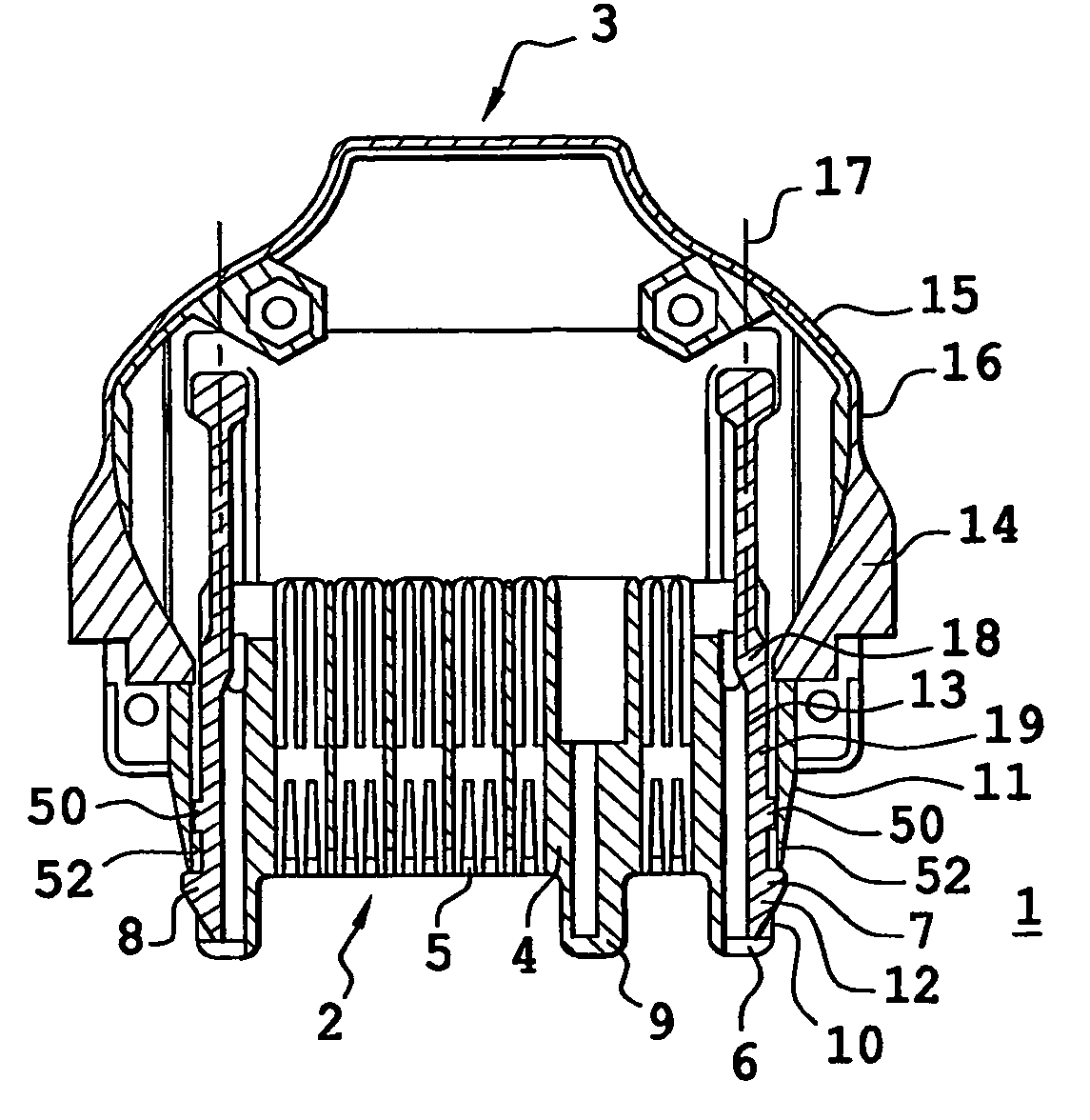
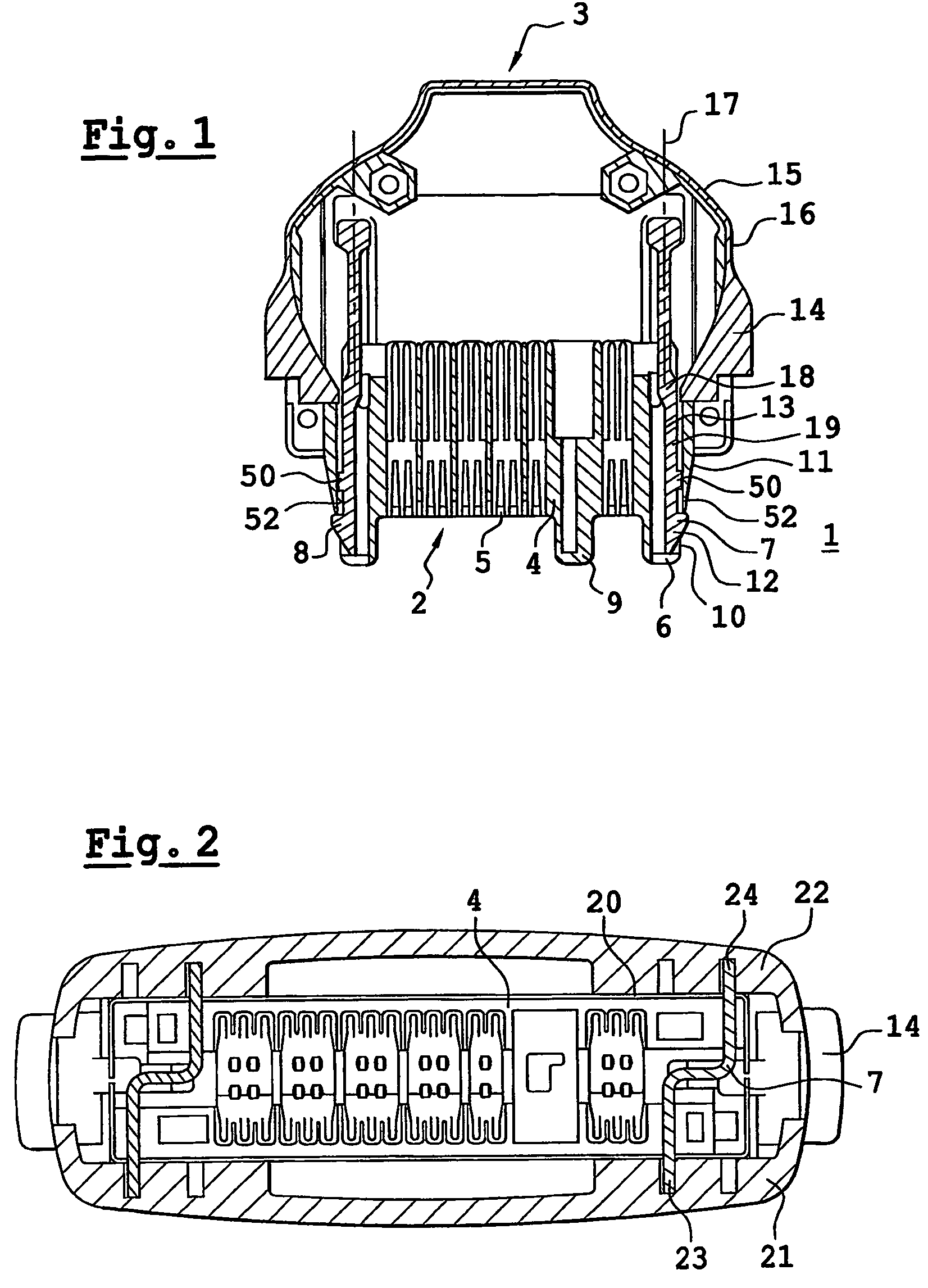
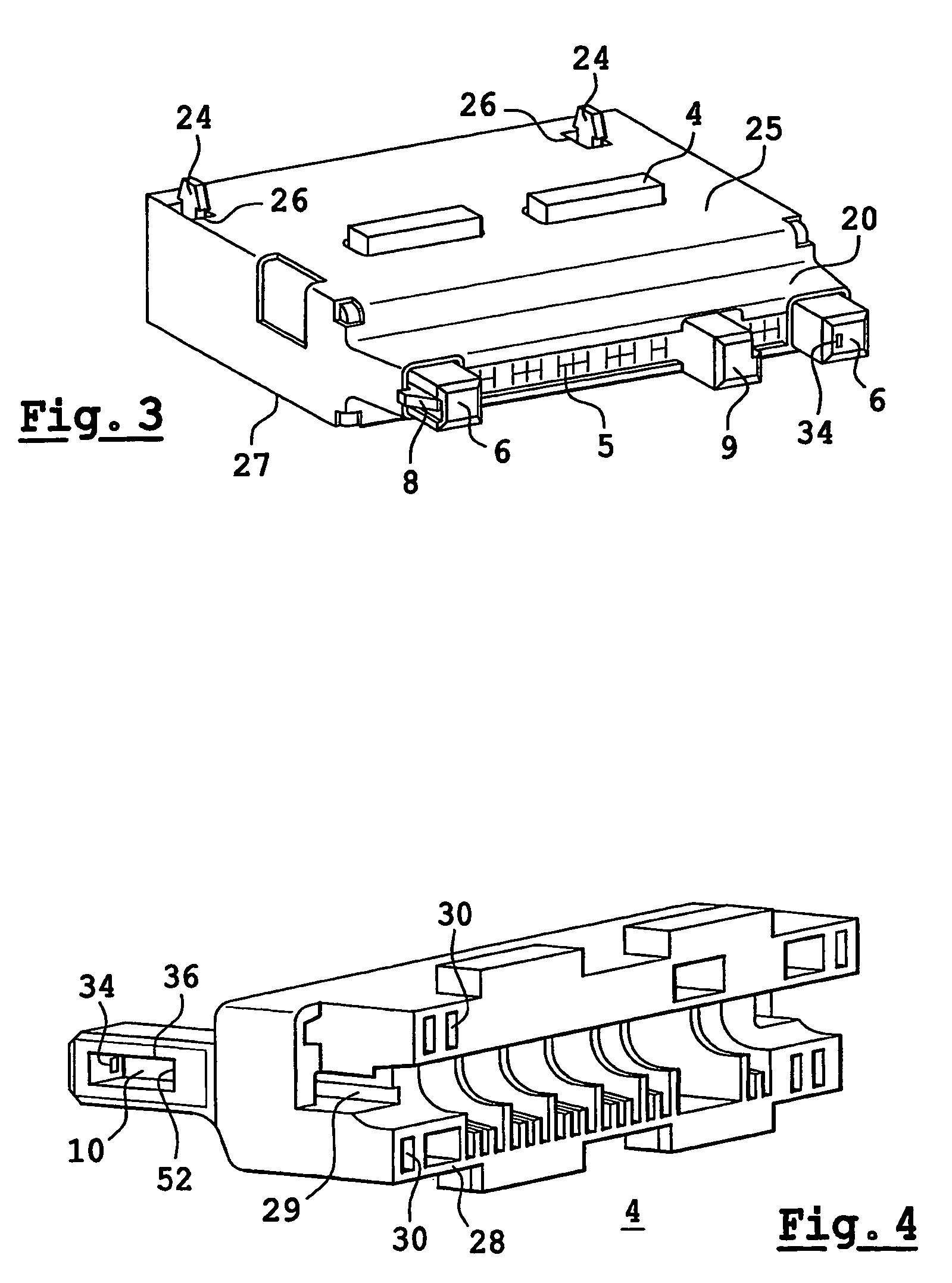
FIELD OF THE INVENTION[0001]The object of the present invention is a plug connector provided with means for lateral locking intended to ensure the retention of the plug connector on a complementary device. It is used more particularly in the domain of electrical plug connectors fitted to the ends of cables with the intention of connecting the said cable to the complementary device, such as a complementary plug connector jack on a mobile telephone. The object of the invention is to propose a locking arrangement which will not occupy excessive space in the interior of the plug connector, and which will also ensure good retention, particularly resistance to tearing which is capable of resisting traction forces of the order of 10 kg.BACKGROUND OF THE INVENTION[0002]In the prior art, plug connectors are known which are fitted to the ends of cables in such a way that the strands of a cable are connected in the interior of a plug connector with the contacts of this plug connector. The cont...

Claims


Application Information

Patent Timeline
IPC IPC(8): H01R13/627
CPCH01R13/6275
Inventor LE GALLIC, HERVESEJOURNE, DAMIENLEROYER, SERGE
Owner FRAMATOME CONNECTORS INT SA
Why Eureka
Try Eureka