
Fill pump piston centering support

Inactive Publication Date: 2005-03-29
TETRA LAVAL HLDG & FINANCE SA
View PDF3 Cites 3 Cited by
  • Summary
  • Abstract
  • Description
  • Claims
  • Application Information

AI Technical Summary

Benefits of technology

The present centering support improves alignment or centering of the piston. Such a centering system reduces the opportunity for the piston to contact the cylinder wall and as such reduces the wear on the pump diaphragm. Advantageously, such a centering system does not adversely effect the ability to accurately dose the amount of product transferred during the pump stroke, and, by permitting a reduced gap between the piston and cylinder it does not reduce significantly the amount of product transferred during each pump stroke.

Problems solved by technology

Although such an arrangement functions well to isolate the product from the moving mechanical components, because the diaphragm is positioned between the stationary cylinder wall and the moving piston, it is subject to wear by virtue of the rubbing of the surfaces.
In addition, in the event that the piston is not aligned within the cylinder, there exists the potential for the diaphragm to rupture or otherwise fail prematurely (e.g., debraid, separate) as a result of the piston coming too close to the cylinder wall.
However, as the gap between the piston and cylinder wall increases, the volume of product moved (per pumping stroke) is subject to changes.
This is problematic in that the volume of product pumped is a “measured” volume as such, the flow rate must be maintained at a precisely controlled rate.

Method used


Image

  • Fill pump piston centering support
  • Fill pump piston centering support
  • Fill pump piston centering support

Examples


Embodiment Construction

While the present invention is susceptible of embodiment in various forms, there is shown in the drawings and will hereinafter be described a presently preferred embodiment with the understanding that the present disclosure is to be considered an exemplification of the invention and is not intended to limit the invention to the specific embodiment illustrated.

It should be further understood that the title of this section of this specification, namely, “Detailed Description Of The Invention”, relates to a requirement of the United States Patent Office, and does not imply, nor should be inferred to limit the subject matter disclosed herein.

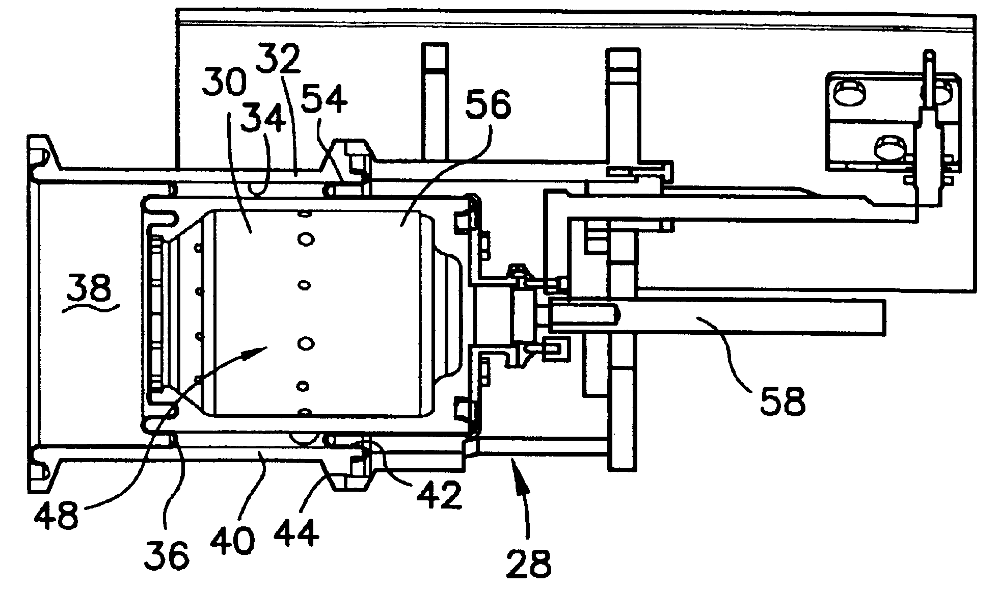
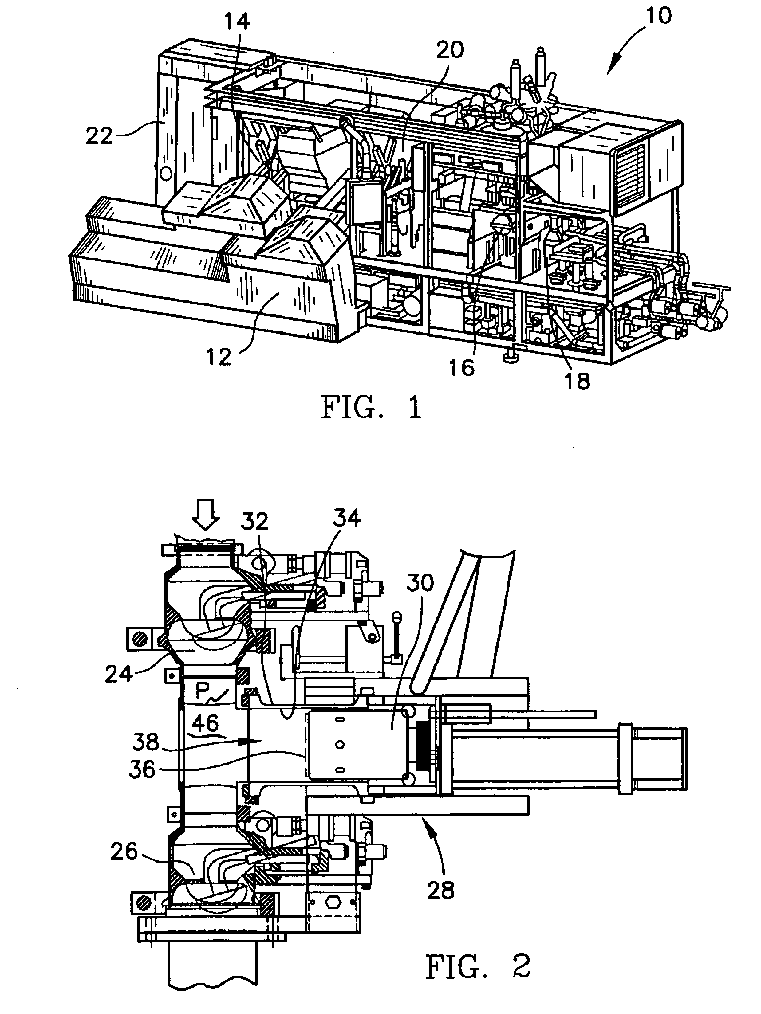
Referring now to the figures and in particular to FIG. 1, there is shown a form, fill and seal packaging machine 10 that is configured to store a series of carton blanks in a flat, folded form, erect the blanks into a tubular form, fold and seal the bottom flaps of the carton, fill and seal the cartons as they move through the machine. The form, fil...


PUM


Abstract

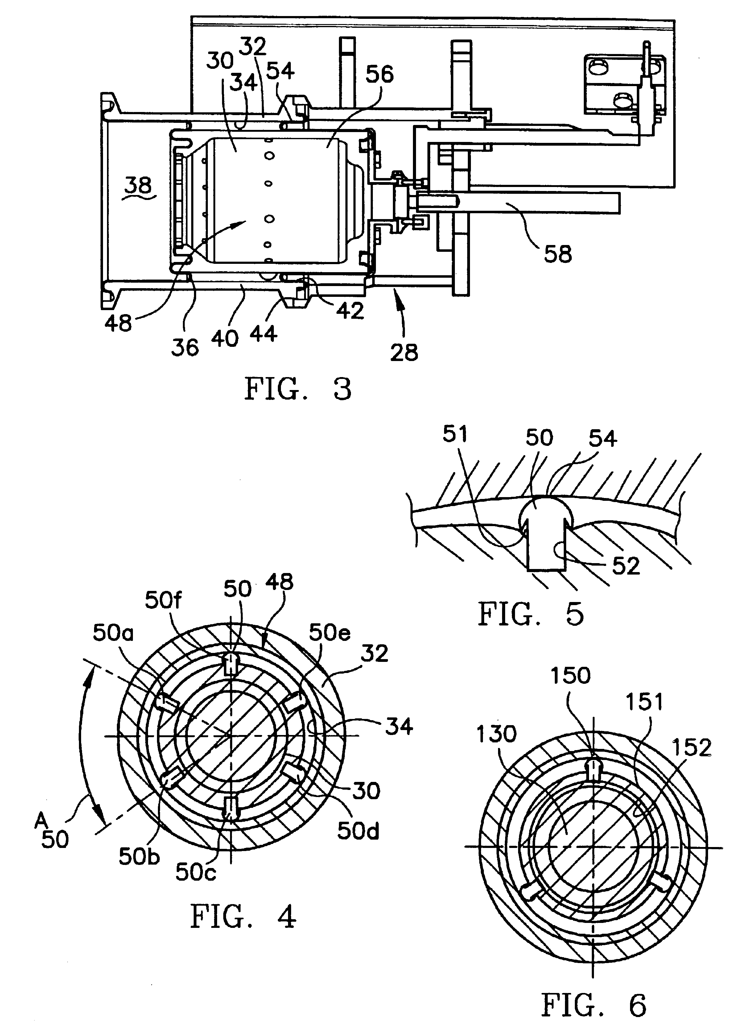
A centering support for a piston in a piston-type pump having a diaphragm extending between the piston and the cylinder to define a product end of the pump and a driven end of the pump includes at least three equally radially spaced, centering elements extending radially outwardly from the piston for contacting the cylinder wall. The centering elements define a gap between the piston and the cylinder wall. The centering elements are disposed on the piston spaced from the diaphragm at the product end of the pump.

Description

BACKGROUND OF THE INVENTIONThe present invention is directed to a support for a fill pump piston. More particularly, the present invention is directed to a support for a piston in a piston-type fill pump for use in a form, fill and seal packaging machine.Form, fill and seal packaging machines are well known in the art. These machines are widely used in the food packaging industry for forming a package, filling the package with a liquid or solid food (or a mixture of liquid and solid foods), and sealing the package after filling. In many such machines, piston pumps are used to move or transport product (e.g., food product) from, for example, a storage tank to individual packages. Piston-type pumps provide for the requisite control over the flows and flow rates of the product.In addition, in such machines, sterilization, generally, must be kept at a maximum. That is, all of the food or product contacting surfaces must be maintained at a high level of cleanliness in order to reduce the...

Claims


Application Information

Patent Timeline
IPC IPC(8): F04B43/02
CPCF04B43/02F01B19/00
Inventor WARNE, WAYNEHERMODSSON, GORANSVEDBERG, AKEKATSUMATA, YOSHIKI
Owner TETRA LAVAL HLDG & FINANCE SA
Learn More