Ligation clip and clip applier

a technology of ligation clips and applicators, applied in the field of mechanical devices, can solve the problems of difficult removal or repositioning, variable force applied by the ligation clips to the vessel, and difficulty in removing or repositioning,

Inactive Publication Date: 2007-04-24
MICROLINE SURGICAL INC
View PDF189 Cites 508 Cited by
  • Summary
  • Abstract
  • Description
  • Claims
  • Application Information

AI Technical Summary

Benefits of technology

[0025]Still another object of the present invention is the provision of improved ligation clips and applicator t

Problems solved by technology

Such crushing actions, of course, permanently deform the clips, making them difficult to remove or re-position.
Prior art surgical ligation clips have several inherent problems.
For example, the force applied by the clip to the vessel can be variable and inconsistent from one clip to the next, because of the variation in crushing force applied to the clip by the user.
Further, prior art clips have a tendency to slip off the end of the blood vessel stub (i.e., perpendicular to the axis of the vessel) to which it has been applied, because of the low coefficient of friction associated with the clip, and lack of adequate restraining force provided by the clip.
A related problem found in the prior art is the fact that the ligating or restraining force offered by the crushed clip varies along the length of the clip, decreasing toward the open end.
Thus, the section of the vessel near the open end of th

Method used


Image

  • Ligation clip and clip applier
  • Ligation clip and clip applier
  • Ligation clip and clip applier

Examples


Embodiment Construction

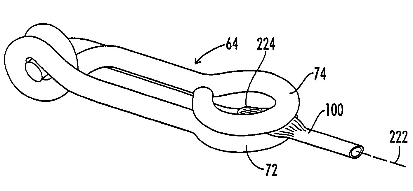
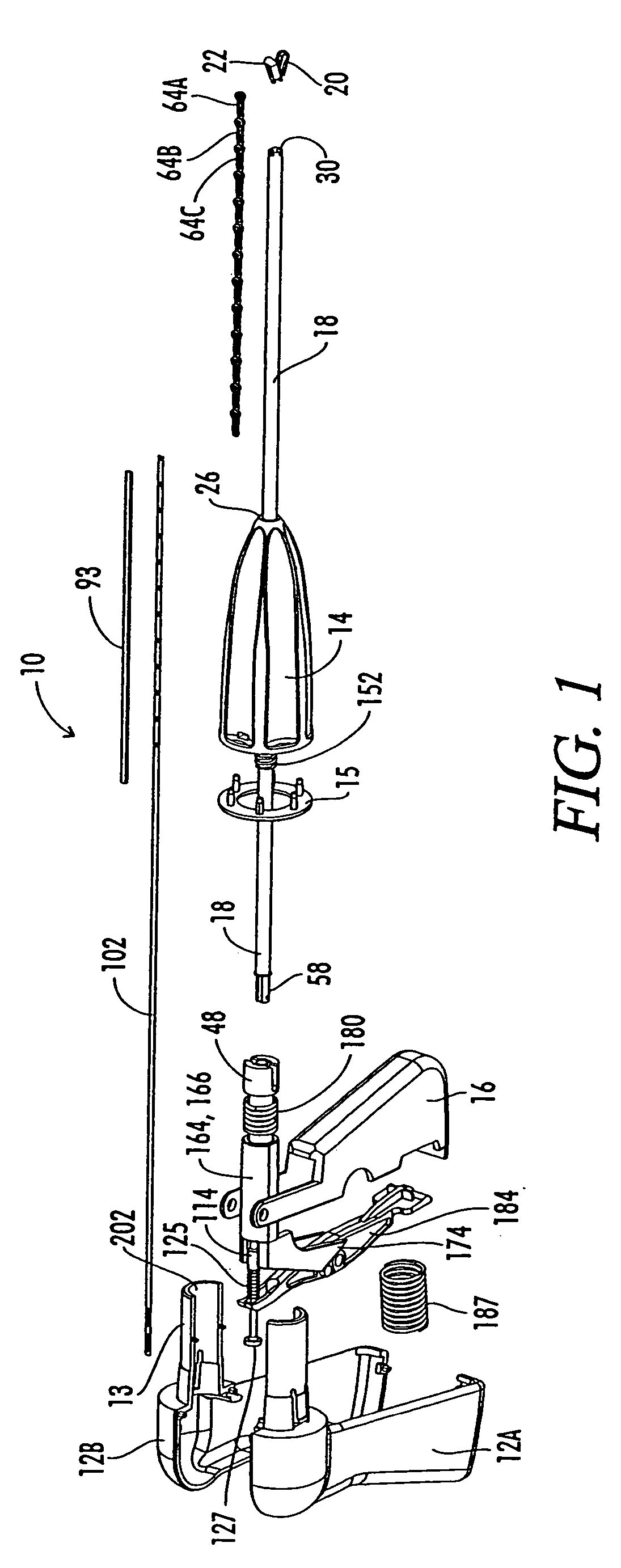
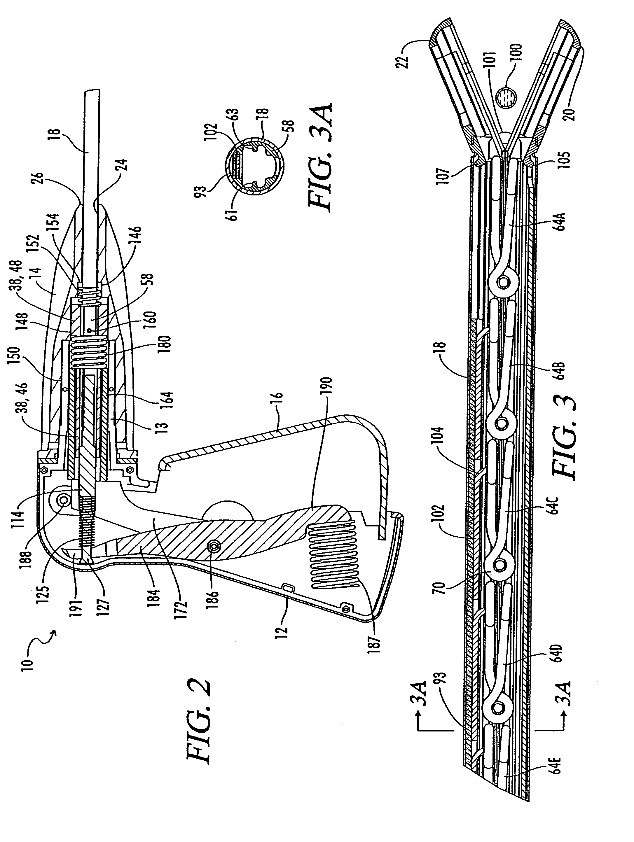
[0071]Referring now to the drawings, and particularly to FIGS. 1–7, a surgical clip applicator apparatus is there shown and generally designated by the numeral 10. The apparatus 10 includes a body or handle portion 12, a barrel portion 14, a trigger 16, an outer tube 18, and first and second articulated jaws 20 and 22.

[0072]As seen in the exploded view of FIG. 1, the handle portion 12 is formed from two molded plastic handle portion halves 12A and 12B. A cylindrical forwardly extending handle projection 13 is integrally formed with the handle 12. A barrel 14 which is also referred to as a rotator 14, is received over the cylindrical extension 13. A rotator ring 15 is attached to the rear end of the barrel 14. The barrel or rotator 14 and the attached tube 18, can be rotated about its longitudinal axis relative to handle 12.

[0073]It is noted that in this disclosure the terms forward and rearward are utilized from the viewpoint of a person holding the apparatus 10, so that the forward...


PUM


Abstract

The ligation clip applicator and ligation clip design are provided which are particularly applicable to placement of a surgical ligation clip during a laparoscopic surgical procedure. The clip includes a support member and a clamping arm having enlarged portions thereon. The applicator device has a magazine including first and second longitudinally extending partially closed channels within which the enlarged portions of the support member and the clamping arm are received with the clip held in an open position. First and second articulated jaws are attached to the magazine and have first and second channel extensions therein aligned with the first and second channels of the magazine, so that a clip can be received from the magazine in the jaws with the first and second enlarged portions of the support member and the clamping arm being received in the first and second channel extensions of the jaws. The channel extensions include first and second releasing openings. The jaws are closed about a vessel to pre-clamp the vessel. The clip is pushed forward into the jaws to a position where the enlarged portions of the support member and the clamping arm are aligned with the releasing openings and the support member and the clamping arm are released allowing the support member and the clamping arm to move toward each other to ligate the vessel therebetween.

Description

[0001]This application is a continuation of application Ser. No. 10 / 082,915, filed Feb. 25, 2002, now U.S. Pat. No. 6,652,545; which is a divisional of application Ser. No. 09 / 258,943, filed Mar. 1, 1999, now U.S. Pat. No. 6,350,269; all of which are incorporated herein by reference.BACKGROUND OF THE INVENTION[0002]1. Field of the Invention[0003]The present invention relates generally to mechanical devices used in surgical procedures to obtain ligation or hemostasis, and more particularly, to low profile tools that can apply a pre-formed, spring loaded ligation clip used during surgery to clamp around a vessel or duct, such as the cystic duct, and thereby obtain ligation.[0004]2. Description of the Prior Art[0005]It will be appreciated by those skilled in the art that the use of ligation clips to control bleeding during surgical procedures is will known. As described, for example, in U.S. Pat. Nos. 4,976,722 and 4,979,950 prior art clips are generally formed of metal wire, usually a...

Claims


Application Information

Patent Timeline
IPC IPC(8): A61C17/12A61B17/122A61B17/10A61B17/128
CPCA61B17/1227A61B17/1285
Inventor SHIPP, JOHN I.SHEPARD, STEVEN Y.SATTERFIELD, JAMES A.
Owner MICROLINE SURGICAL INC
Why Eureka
Try Eureka