Beam steering apparatus

a technology of beam steering and beam, which is applied in the direction of electrical apparatus, electrical transmission, electromagnetic transmission, etc., can solve the problems of bulky and costly arrangements, and achieve the effect of reducing signal loss and dispersion

Inactive Publication Date: 2007-04-24
BAE SYSTEMS PLC
View PDF12 Cites 5 Cited by
  • Summary
  • Abstract
  • Description
  • Claims
  • Application Information

AI Technical Summary

Benefits of technology

[0017]Preferably, each optical carrier has a different frequency to that of the other carriers. This has the advantage that a number of different modulated optical carriers may pass through the same section of optical fibre without interference taking place between those carriers. Preferable the optical carriers are generated by lasers.
[0018]Thus in embodiments of the invention a given second delay unit is effectively re-used by a plurality of first delay units, which means that duplication of second delay units is minimised. Furthermore, different modulated optical carriers may be combined in a single optical fibre for input to a second delay unit that is linked to a number of first delays units so that each of the combined modulated optical carriers are delayed simultaneously, by a selected amount, without needing to separate the different modulated optical carriers.
[0021]In preferred embodiments of the present invention optical fibre is used as the transmission medium. This has several advantages in comparison with the prior art use of cables to convey radio frequency signals through a series of delay circuits. In particular, in using optical fibre, signal losses and dispersion effects may be reduced and the resulting apparatus provides a physically compact and stable solution that is resistant to electro-magnetic interference. In this embodiment, signals modified by the first delay units are collected into the same waveguide prior to modification by the second delay unit, and are only combined into a single output signal after when the second time delay unit has applied the third or fourth amount of time delay and the resultant signals have been demultiplexed and demodulated. The beam steering apparatus comprises a demultiplexing device, preferably a wavelength division demultiplexing device, arranged to separate out the respective modulated carriers from the waveguide, and a demodulating unit arranged to demodulate the carriers from the optical domain into the radio frequency domain, at which point the signals are combined.

Problems solved by technology

Many different signal processing systems are faced with the problem of capturing signals that emanate from different directions.
A problem with these systems is that the transmission lines occupy physical space, and, for a large array of antenna elements, many different lengths of transmission lines are required, which results in bulky and costly arrangements.

Method used


Image

  • Beam steering apparatus
  • Beam steering apparatus
  • Beam steering apparatus

Examples


first embodiment

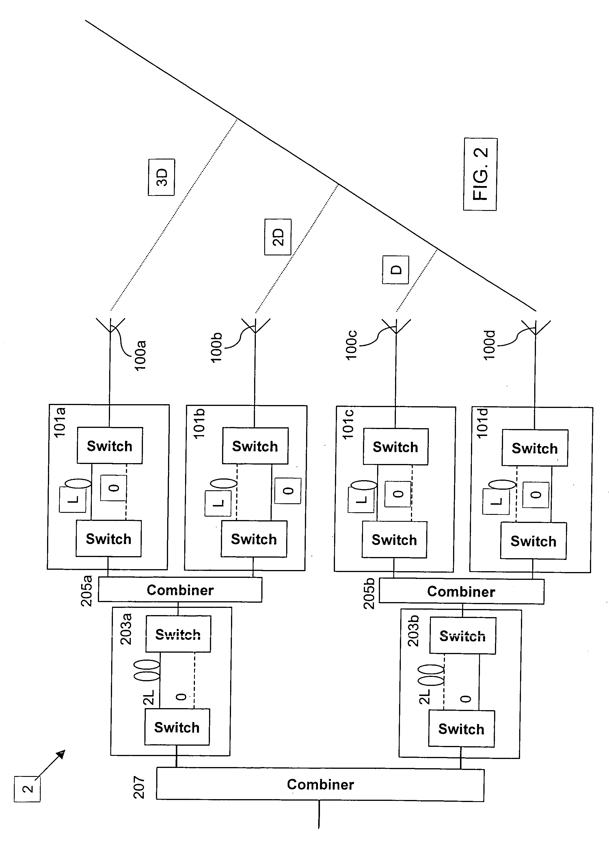
[0039]Embodiments of beam steering apparatus according to the invention will now be described with reference to FIGS. 2 and 3. Turning firstly to FIG. 2, in the invention, referred to herein as a beamformer, the beamformer 2 comprises a plurality of first delay units 101a . . . 101d, each of which is arranged to apply an amount of time delay to signals transceived by a respective antenna element, and a plurality of second delay units 203a, 203b, each of which is arranged to apply an amount of time delay to signals that have been modified by the first delay units 101a . . . 101d. At least one 203a, and preferably both 203a, 203b, of the second units are connected to two first delay units 101a, 101b via a combiner unit 205a, 205b, which, in the case of combiner unit 205a, is arranged to combine signals that have been modified by the associated first delay units 101a, 101b, and in the case of combiner unit 205b, is arranged to combine signals that have been modified by the associated f...

second embodiment

[0047]Whilst in the second embodiment the delay units are provided by OEIC, they could alternatively be provided by suitable mechanical switches.

[0048]Whilst in the above embodiments the entire beamformer is shown to be configured in accordance with the invention, the hierarchical arrangement of first delay units and second delay units could alternatively be applied to a selected part of the beamformer.

[0049]Whilst in the above embodiments the delay unit arrangement includes one switchable delay unit at each node, the arrangement could alternatively comprise a plurality of two-way switchable delay units arranged in series at each node in at least the highest level nodes of the hierarchy (the antenna element level.) Each such a series would consist of delay units having progressively smaller time delay differences between their two respective settings (e.g. L, L / 2, L / 4, etc.), whereby a variety of time delays may be applied at selected increments (e.g. L / 4) at each element. Thus, a v...


PUM


Abstract

A beam steering apparatus including an antenna array having a plurality of antenna elements. The antenna elements are spatially arranged with respect to one another and being operable to receive signals. A plurality of optical modulators, each of which is associated with a different one of the antenna elements and are operable to modulate signals received thereby onto a different respective optical carrier. A plurality of delay units for applying an amount of delay to modulated optical signals passing therethrough in respect of one or more of the antenna elements. A demultiplexer for separating the modulated optical carriers within an optical signal output by the delay units. A demodulator for demodulating the signal received by each antenna element from the respective separated modulated optical carrier. A combiner for combining the demodulated received signals output by the demodulator.

Description

[0001]This application is the US national phase of international application PCT / GB2004 / 003840 filed Sep. 8, 2004, which designated the US and claims priority to GB Application No. 0321350.1 filed 12 Sep. 2003 and EP Application No. 03255736.5 filed 12 Sep. 2003. The entire contents of these applications are incorporated herein by reference.FIELD OF THE INVENTION[0002]The present invention relates to beam steering apparatus and is suitable, particularly but not exclusively, for use with antennas arranged to transceive radio frequency signals.BACKGROUND OF THE INVENTION[0003]Many different signal processing systems are faced with the problem of capturing signals that emanate from different directions. Examples of such systems include Radio Frequency (RF) base stations, air traffic control systems, and satellite systems (to name a few), which either employ mechanical devices comprising an antenna that physically moves in space, or electronic devices comprising antenna elements that ap...

Claims


Application Information

Patent Timeline
Patent Type & Authority Patents(United States)
IPC IPC(8): H01Q3/22H01Q3/26
CPCH01Q3/2676
Inventor EASTON, NICHOLAS J
Owner BAE SYSTEMS PLC
Why Eureka
Try Eureka