Video apparatus with video signal detection and respective method for recognizing a video signal

Inactive Publication Date: 2007-04-24
THOMSON LICENSING INC
View PDF5 Cites 9 Cited by
  • Summary
  • Abstract
  • Description
  • Claims
  • Application Information

AI Technical Summary

Benefits of technology

[0010]The invention provides a user therefore with an automatic setup to view a video signal from a video appliance, which comprises a video output according to one of the known video standards, and which may comprise in particular a component video signal output. A user therefore does not need to understand the video signal standards available at the output of the video appliance and does not have to select a specific input video type. This could be done for example with an on-screen-display (OSD) of a television set connected to the video appliance, the on-screen-display providing a list of the possible input video types. The invention therefore saves software memory for the instruction sets, which would have been necessary in the on-screen-display of the video display appliance for the selection of the video input types. It avoids also respective information in the user manual and translations of the user manual for the countries, in which the video apparatus is sold.
[0011]It is therefore possible to detect component video signals with the synchronization signal detector by means of the microcontroller. The invention is useful in particular for television sets, analog or digital video recorders, audio / video (A / V) receivers, and any other appliances comprising a video input for several television standards and a synchronization signal detector.

Problems solved by technology

But because this video standard needs three separate signal lines with a high bandwidth for each signal, this standard is rarely used for consumer electronics appliances.
Because luminance and chrominance signals are closely superposed in this standard, a perfect separation of the luminance and the chrominance signal in a television receiver is not possible and leads for example to cross color and cross luminance distortions.

Method used


Image

  • Video apparatus with video signal detection and respective method for recognizing a video signal
  • Video apparatus with video signal detection and respective method for recognizing a video signal

Examples


Embodiment Construction

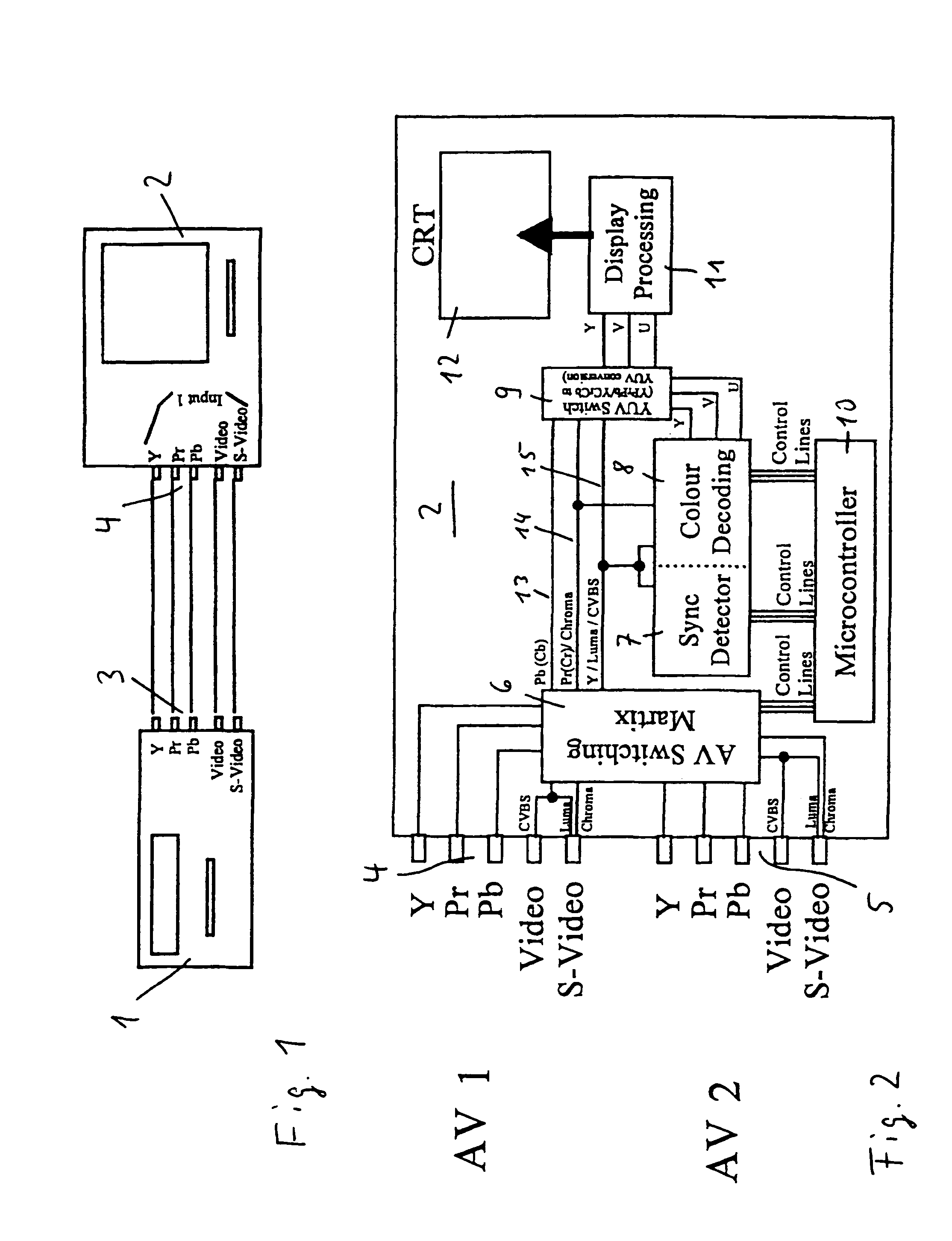
[0015]In FIG. 1 a DVD player 1 is shown comprising video output terminals 3 according to the known video standards Video, for example CVBS, S-Video providing S-VHS video signals, and a component video signal output YPrPb for providing a component video signal. A specific video output may be selected by a user, or the video signal may be applied to all video outputs of the DVD player, when playing a DVD. As explained before, for highest picture quality the component video signal output is preferred.

[0016]The DVD player 1 is connected to a video apparatus, in this embodiment to a television set 2, which comprises a video input 4 to which the outputs of the DVD player 1 are coupled. The television set usually comprises further video inputs, not shown in FIG. 1, to which other video sources, for example a video recorder or a settop box, can be connected.

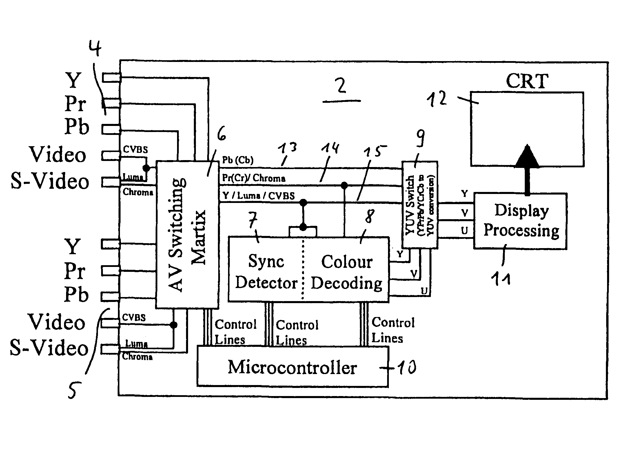
[0017]In FIG. 2 the television set 2 is shown in more detail, especially the input section of the television set 2. As explained before...


PUM


Abstract

A video apparatus comprises an input switching matrix, to which a video input is coupled, the video input comprising a terminal for a component video signal and a CVBS terminal and / or a S-VHS terminal, a synchronization signal detector and a color decoder coupled to the input switching matrix, an output switching matrix coupled to the input switching matrix and to the color decoder, and a microcontroller coupled to the input switching matrix and to the synchronization signal detector for controlling the input switching matrix. The detection of the component video signal is made automatic by means of the microcontroller, the synchronization signal detector and the color decoder.

Description

FIELD OF THE INVENTION[0001]This application claims the benefit under 35 U.S.C. § 365 of European patent application No. 03004542.1 filed Feb. 28, 2003.[0002]The invention relates to a video apparatus comprising a video input, an input switching matrix coupled to the video input, a synchronization signal detector coupled to a luminance output of the input switching matrix and a color decoder being coupled to a color output and also to the luminance output of the input switching matrix. An apparatus of this kind is known for example from a television set or a video recorder, which comprise several audio / video (AV) inputs, to which other video appliances, for example a DVD player or a video recorder, can be coupled.BACKGROUND[0003]For the transmission of video signals between consumer electronics video appliances, several interface standards are known. The best video quality can be provided by so-called R, G, B signals, in which the three colors red, green and blue are provided each a...

Claims


Application Information

Patent Timeline
IPC IPC(8): H04N5/268G09G5/00H04N5/18H04N9/00H04N9/64
CPCH04N9/641A01G9/021A01G9/083
Inventor BYRNE, GRAHAM
Owner THOMSON LICENSING INC
Why Eureka
Try Eureka