Laser radar apparatus

a laser radar and apparatus technology, applied in the direction of speed/acceleration/shock measurement, measurement devices, instruments, etc., can solve the problems of laser radar apparatus not being able to detect the quality of scatterers in the atmosphere, the method exhibits weak coherence of the doppler signal, and the difficulty in effectively improving the s/n ratio of the received ligh

Inactive Publication Date: 2007-04-24
MITSUBISHI ELECTRIC CORP
View PDF15 Cites 2 Cited by
  • Summary
  • Abstract
  • Description
  • Claims
  • Application Information

AI Technical Summary

Benefits of technology

[0014]In accordance with the present invention, there is provided a laser radar apparatus including a frequency conversion means for converting the frequency of an electric signal outputted from a photoelectric conversion means into a baseband frequency by using a modulating signal generated by an oscillation means. The laser radar apparatus carries out a coherent integral of the electric signal whose frequency has been converted by the frequency conversion means, and measures the quality of scatterers which exist in the atmosphere from a result of the integral. As a result, even when the S / N ratio of the light signal received by a receiving means is low, the laser radar apparatus can detect the quality of the scatterers.

Problems solved by technology

As mentioned above, although the prior art laser radar apparatus employs a method of detecting the Doppler shift frequency for the carrier frequency of the laser light, it is known that this method exhibits weak coherency of the Doppler signal.
Thus, when the coherent time of the Doppler signal is short, an incoherent integral of the Doppler signal is carried out so as to obtain an improvement in the S / N ratio of the received light, but it is known that it is difficult to effectively improve the S / N ratio of the received light even if an incoherent integral of the Doppler signal is carried out.
A problem with the prior art laser radar apparatus constructed as mentioned above is that while it can acquire a Doppler signal having a long coherent time, when the S / N ratio of received light is low, there is a possibility that the prior art laser radar apparatus is not able to detect the quality of scatterers in the atmosphere since it has no means for improving the S / N ratio of received light.

Method used


Image

  • Laser radar apparatus
  • Laser radar apparatus
  • Laser radar apparatus

Examples


embodiment 1

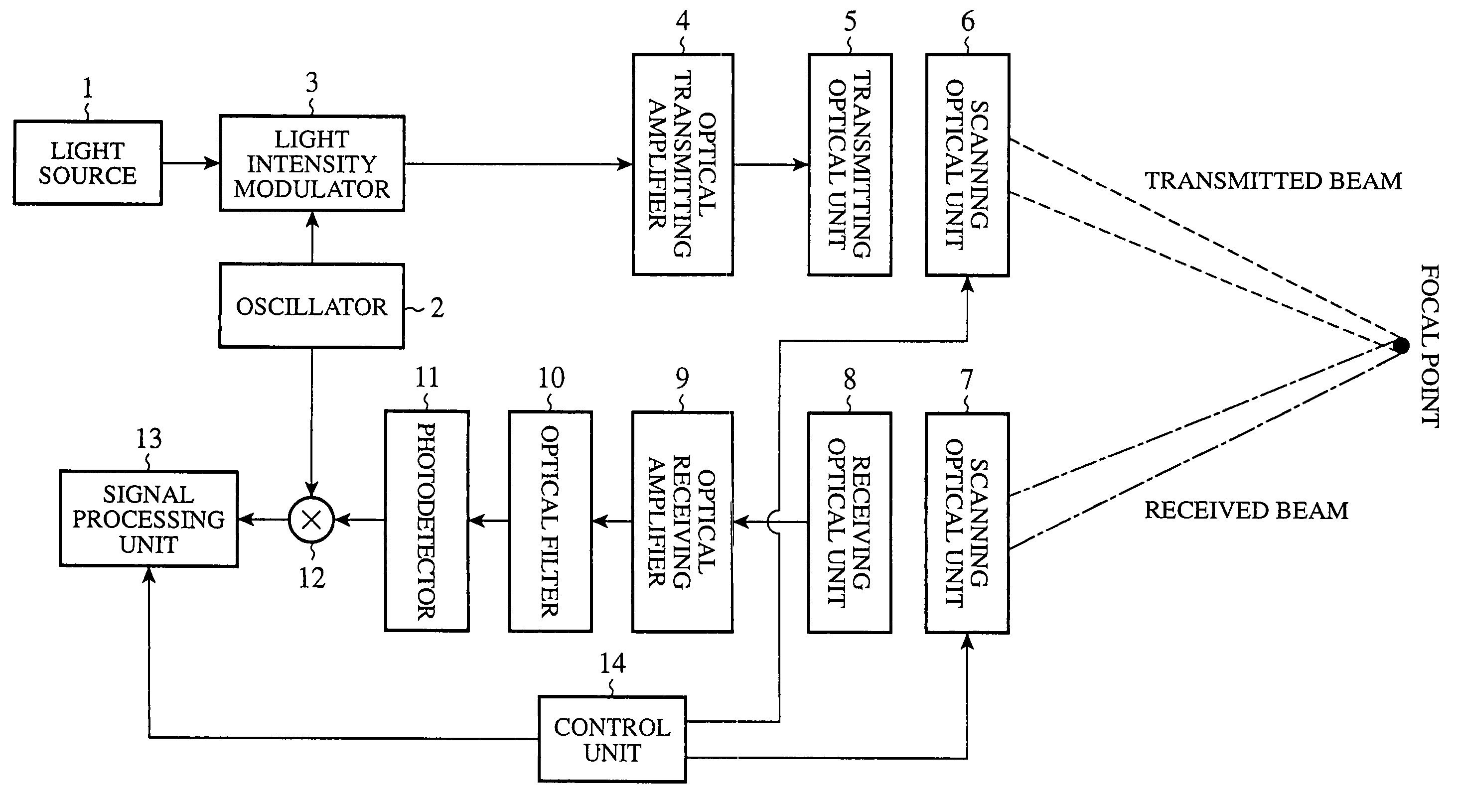
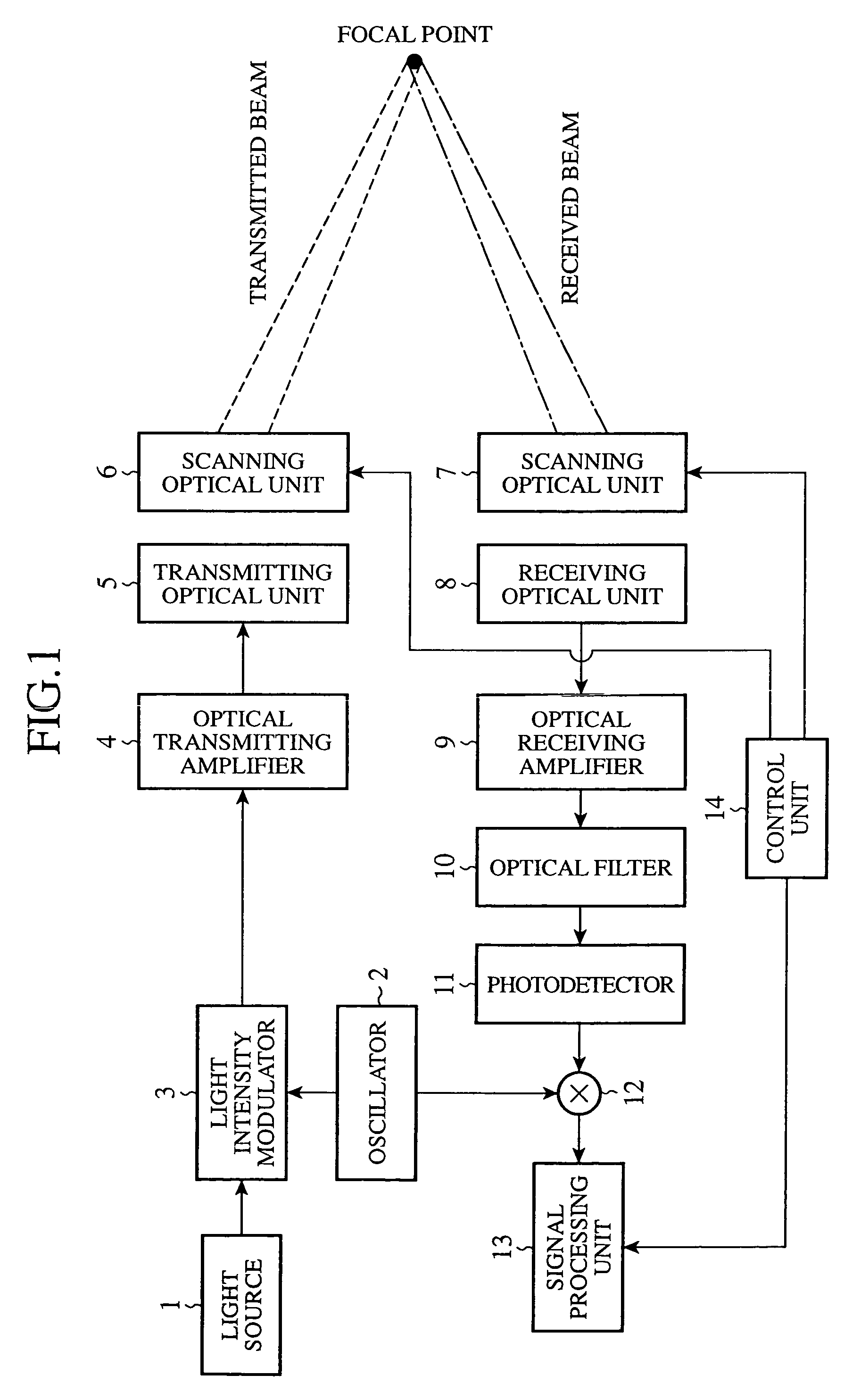
[0024]FIG. 1 is a block diagram showing a laser radar apparatus according to embodiment 1 of the present invention. In the figure, a light source 1 transmits a light signal which consists of a continuous wave, and an oscillator 2 generates a modulating signal which consists of a continuous wave. The oscillator 2 constitutes an oscillation means.

[0025]A light intensity modulator 3 performs an intensity modulation on the light signal transmitted from the light source 1 using the modulating signal generated by the oscillator 2. The light intensity modulator 3 constitutes a modulation means.

[0026]An optical transmitting amplifier 4 amplifies the light signal intensity-modulated by the light intensity modulator 3, and a transmitting optical unit 5 transmits the light signal amplified by the optical transmitting amplifier 4 into the atmosphere by way of a scanning optical unit 6. The optical transmitting amplifier 4, the transmitting optical unit 5, and the scanning optical unit 6 constit...

embodiment 2

[0078]In accordance with above-mentioned embodiment 1, the laser radar apparatus converts the frequency of the electric signal into a baseband frequency by using the mixer 12, as previously explained. In contrast, a laser radar apparatus in accordance with embodiment 2 is so constructed as to use an IQ detector circuit, instead of the mixer 12, and to make the IQ detector circuit output an IQ video signal as a Doppler signal.

[0079]Thereby, the signal processing unit 13 can identify not only the absolute value of the air velocity but the sign + or − of the air velocity, i.e., whether the blowing winds are following or head ones.

embodiment 3

[0080]In accordance with above-mentioned embodiment 1, the laser radar apparatus is equipped with the transmitting optical unit 5 and the receiving optical unit 8, as previously explained. In contrast, a laser radar apparatus in accordance with embodiment 3 is so constructed as to have one optical member provided with the functionalities of the transmitting optical unit 5 and the receiving optical unit 8.

[0081]This single optical member can be provided with the functionality of an optical circulator. Since the single optical member has a focal point for transmission and a focal location for reception that essentially match with each other, the system can be easily constructed.


PUM


Abstract

A laser radar apparatus includes a mixer 12 for converting the frequency of an electric signal outputted from a photodetector 11 into a baseband frequency by using a modulating signal generated by an oscillator 2. The laser radar apparatus carries out a coherent integral of the electric signal whose frequency has been converted by the mixer 12, and measures the quality of scatterers which exist in the atmosphere from a result of the integral. As a result, even when the S / N ratio of the light signal received by a receiving optical unit 8 is low, the laser radar apparatus can detect the quality of the scatterers.

Description

FIELD OF THE INVENTION[0001]The present invention relates to a laser radar apparatus that transmits and receives laser light and measures the quality of scatterers in the atmosphere.BACKGROUND OF THE INVENTION[0002]By transmitting laser light into the atmosphere, a prior art laser radar apparatus receives laser light which has a Doppler frequency shift due to the drift speed of scatterers in the atmosphere, and carries out heterodyne detection of the laser light and local light so as to detect a Doppler signal.[0003]The prior art laser radar apparatus then acquires the drift speed of the scatterers from the frequency of the Doppler signal.[0004]As mentioned above, although the prior art laser radar apparatus employs a method of detecting the Doppler shift frequency for the carrier frequency of the laser light, it is known that this method exhibits weak coherency of the Doppler signal. In other words, it is known that the coherent time of the Doppler signal is short. For example, whe...

Claims


Application Information

Patent Timeline
Patent Type & Authority Patents(United States)
IPC IPC(8): G01P3/36G01S7/481G01S13/32G01S17/32G01S17/58
CPCG01S17/32G01S17/58G01S7/4818G01S13/325
Inventor KAMEYAMA, SHUMPEIHIRANO, YOSHIHITOASAKA, KIMIOANDO, TOSHIYUKIOKAMURA, ATSUSHIWAKAYAMA, TOSHIOSAKAMAKI, HIROSHI
Owner MITSUBISHI ELECTRIC CORP
Why Eureka
Try Eureka