Coin discriminating method and apparatus

a coin and discrimination technology, applied in the field of coin discrimination methods and apparatuses, can solve the problems of low intensity of light reflected from a flat portion of a coin, and achieve the effect of preventing the apparatus from becoming large and reliable discrimination

Active Publication Date: 2007-04-24
LAUREL PRECISION MACHINES
View PDF7 Cites 15 Cited by
  • Summary
  • Abstract
  • Description
  • Claims
  • Application Information

AI Technical Summary

Benefits of technology

[0006]It is therefore an object of the present invention to provide a coin discriminating method and apparatus and, in particular, to provide a coin discriminating method and apparatus for reliably discriminating whether or not coins are acceptable, the denominations of coins and whether or not coins are damaged to higher than a predetermined level by optically detecting coin surface patterns while preventing the apparatus from becoming large.

Problems solved by technology

In a study done by the inventors of the present invention, it was found that the intensity of light reflected from an edge portion of a coin is generally high but when the coin has been in circulation for a long time and damaged, the resulting wear of the edge portion of the coin causes the bright portion data signal intensity average value obtained from the damaged coin to be lower than that obtained from an undamaged coin, and that, on the other hand, the intensity of light reflected from a flat portion of a coin is generally low but when the coin has been in circulation for a long time and damaged, the resulting irregular light reflection owing to scratching and / or staining of the flat portion of the coin causes the dark portion data signal intensity average value obtained from the damaged coin to be higher than that obtained from an undamaged coin.

Method used


Image

  • Coin discriminating method and apparatus
  • Coin discriminating method and apparatus
  • Coin discriminating method and apparatus

Examples


Embodiment Construction

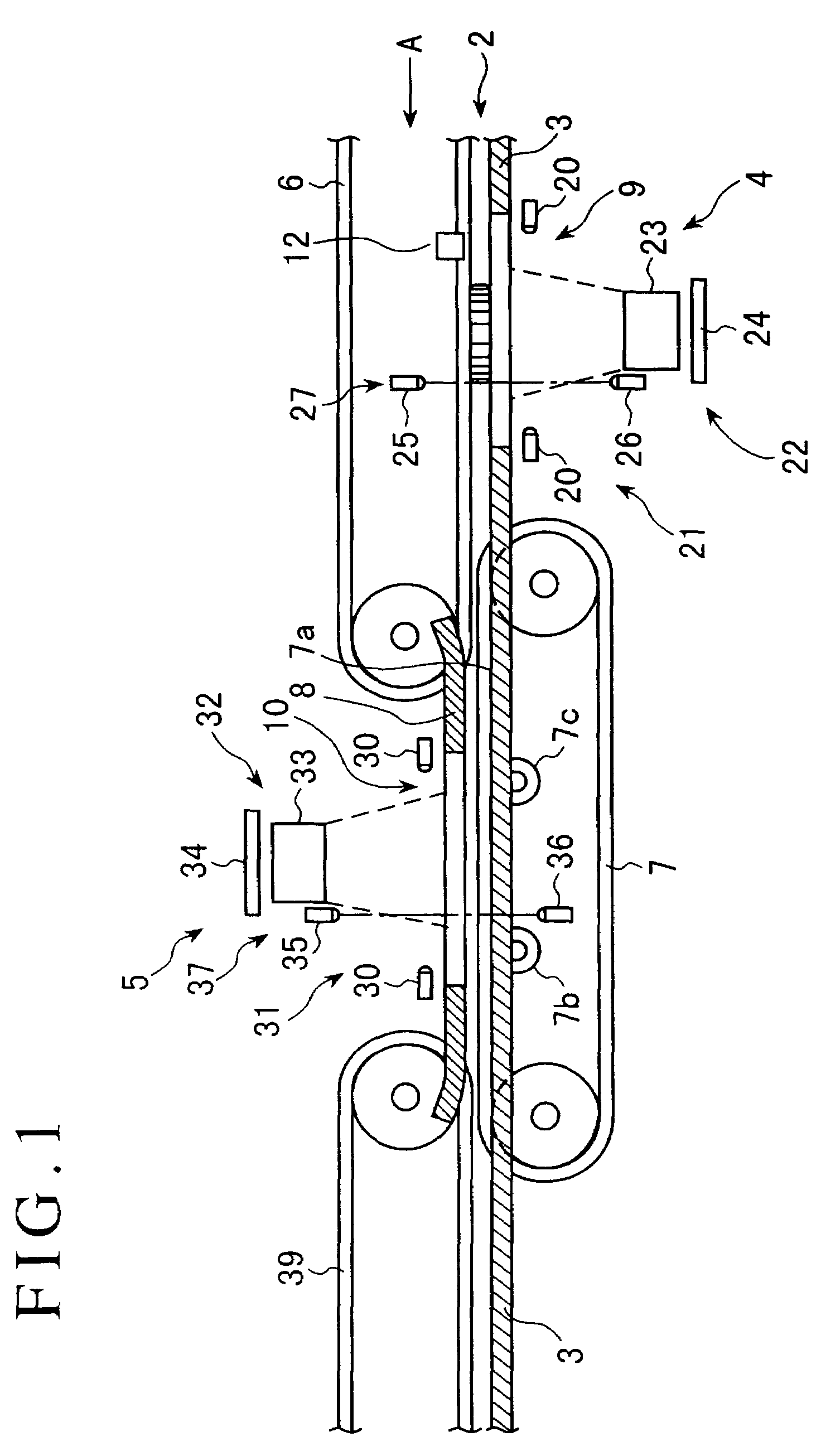
[0046]FIG. 1 is a schematic longitudinal cross-sectional view of a coin discriminating apparatus which is a preferred embodiment of the present invention.

[0047]As shown in FIG. 1, a coin passage 2 through which coins 1 are transported is provided with a coin passage member 3 extending in the transporting direction of the coins 1 over the entire distance that the coins 1 are transported. The coin discriminating apparatus includes a first pattern data detection unit 4 and a second pattern data detection unit 5. In the vicinity of the first pattern data detection unit 4, the coin passage 2 is formed by the coin passage member 3 located below and a transporting belt 6 constituted as an endless round belt. In the vicinity of the second pattern data detection unit 5, the coin passage 2 is formed by a transporting belt 7 constituted as an endless belt located to project upward from an opening 7a formed in the coin passage member 3 and a coin passage forming member 8 located above the trans...


PUM


Abstract

A coin discriminating method includes steps of irradiating a surface of a coin with light, photoelectrically detecting light reflected by the surface of the coin, producing detected pattern data of the surface of the coin, binarizing corresponding reference pattern data so that “1” is assigned to pixel data having a signal intensity level equal to or higher than a predetermined signal intensity level and “0” is assigned to pixel data having a signal intensity level lower than the predetermined signal intensity level to produce reference bright portion pattern data consisting of “1” pixel data and reference dark portion pattern data consisting of “0” pixel data, extracting bright portion pattern data consisting of pixels corresponding to pixels included in the reference bright portion pattern data and dark portion pattern data consisting of pixels corresponding to pixels included in the reference dark portion pattern data from the detected pattern data, and discriminating whether or not the surface of the coin is damaged to higher than the predetermined level by comparing the difference between the bright portion data signal intensity average value and dark portion data signal intensity average value with a threshold value of coins of a corresponding denomination.

Description

BACKGROUND OF THE INVENTION[0001]The present invention relates to a coin discriminating method and apparatus and, in particular, to a coin discriminating method and apparatus for reliably discriminating whether or not coins are acceptable, the denominations of coins and whether or not coins are damaged to higher than a predetermined level by optically detecting coin surface patterns while preventing the apparatus from becoming large.DESCRIPTION OF THE PRIOR ART[0002]There is known a coin discriminating apparatus for discriminating whether or not coins are acceptable, namely, the genuineness of coins, whether or not coins are currently in circulation and the denomination of coins, and discriminating whether or not coins are damaged to higher than a predetermined level.[0003]Japanese Patent Application Laid Open No. 2000-306135 discloses a coin discriminating apparatus which discriminates whether or not coins are acceptable and the denomination of coins by optically detecting surface ...

Claims


Application Information

Patent Timeline
Patent Type & Authority Patents(United States)
IPC IPC(8): G06K9/20G07D5/00G06K9/46G07D5/02G06T1/00G06T7/00
CPCG07D5/005G07D5/00
Inventor TAKAHASHI, MASATAKA
Owner LAUREL PRECISION MACHINES
Why Eureka
Try Eureka