Plural-frequency capacitive occupancy sensing system

a capacitive measurement and sensing system technology, applied in the direction of pedestrian/occupant safety arrangement, vehicular safety arrangement, instruments, etc., can solve the problems of large cores of inductor wound on the cores of the inductor, the inductor may not and the inductor may not be able to operate in sensing mode and heating mod

Active Publication Date: 2015-03-31
IEE INT ELECTRONICS & ENG SA
View PDF10 Cites 9 Cited by
  • Summary
  • Abstract
  • Description
  • Claims
  • Application Information

AI Technical Summary

Benefits of technology

[0012]The inventors have found that the discrimination between a car seat occupancy condition that has to be detected as “occupied” (seat occupied by 5th percentile female or a heavier person) and a car seat occupancy condition that has to be detected as “not occupied” (seat empty or carrying a child restraint system) can be made more reliable by using a threshold capacitance that depends on the difference determined in conductance, susceptance, resistance, reactance and / or capacitance between to frequencies of the measurement signal. Instead of using a variable threshold, it is also possible to apply a correction to the measured capacitance that is compared with the capacitance threshold.
[0025]According to a preferred embodiment of the invention, the antenna electrode comprises (includes as a part or consists of) a heating element, e.g. a heating wire, a heating cable, a film-based heating element, a fibre-based heating element, etc. The heating element may be that of a seat heater. Preferably, the capacitive occupancy sensing system comprises a common mode choke, with which the heating element is DC-couplable to a heating circuit (source of the heating current, thermostat, etc.). As will be appreciated, the common mode choke essentially prevents the first and second signal from passing to the reference node via the heating circuit.

Problems solved by technology

The device may not operate in sensing mode and in heating mode at a time.
A disadvantage of the system disclosed in U.S. Pat. No. 6,703,845 is that the inductors used as AC-decoupling elements have to support the full heating current (up to 10 A DC and more) and present high AC impedance to the capacitive measurement circuit and the seat heater at the same time.
High inductance and high operating DC current implies that the inductor have to be wound on large cores, which are expensive.

Method used


Image

  • Plural-frequency capacitive occupancy sensing system
  • Plural-frequency capacitive occupancy sensing system
  • Plural-frequency capacitive occupancy sensing system

Examples


Embodiment Construction

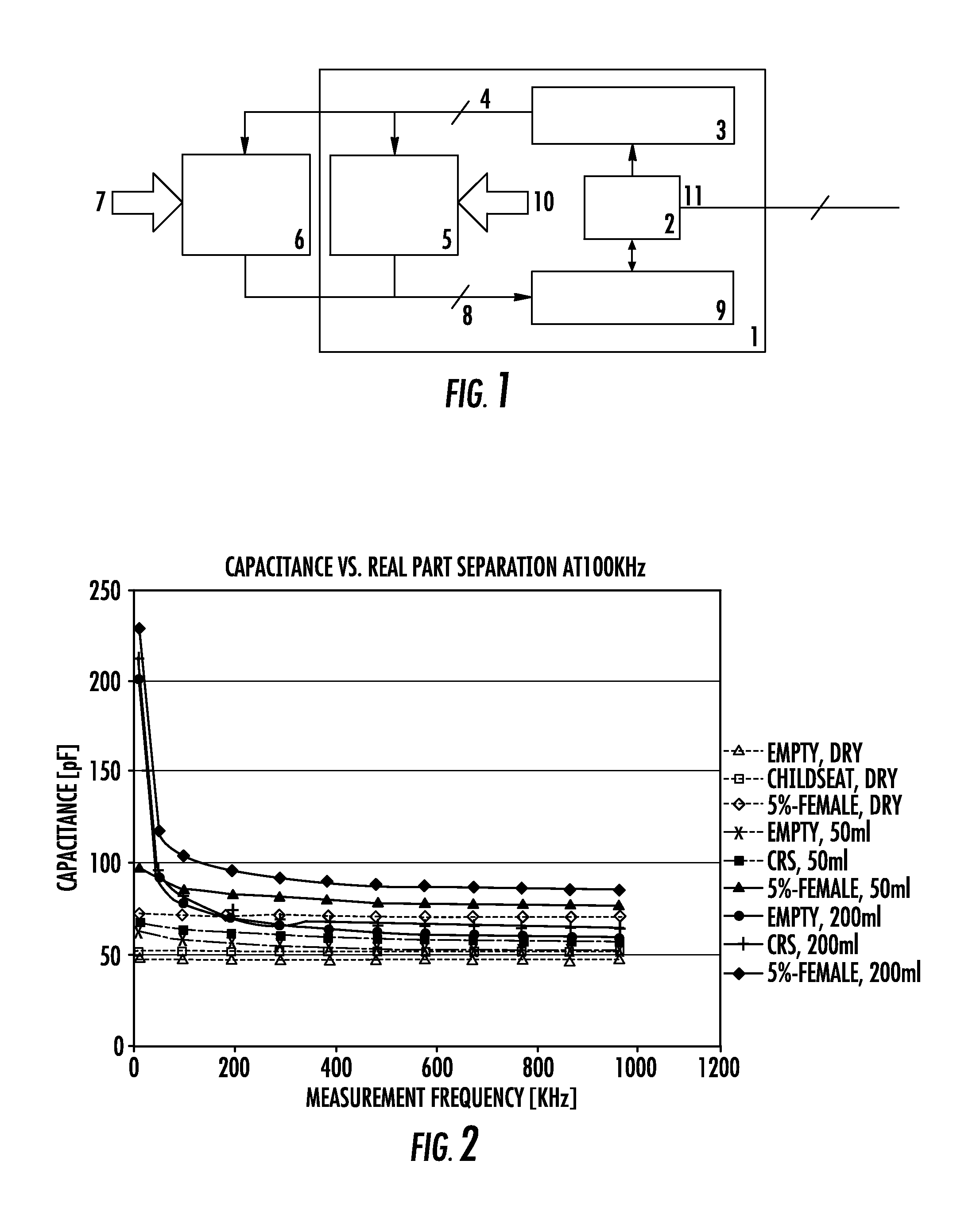
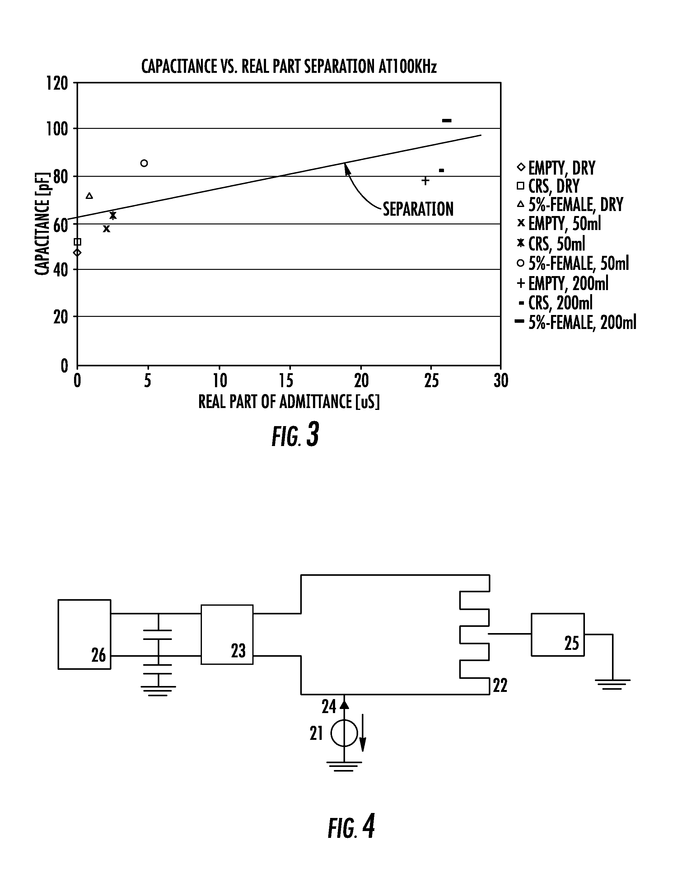
[0035]Capacitive occupant detection systems in the automotive industry, which are used to detect the presence of an occupant in order to activate the airbag in case of a crash, typically determine the occupancy state by measuring the complex impedance / admittance seen by the sensing element (the antenna electrode) arranged in the seat. This sensing element can be one or more electrodes, dedicated exclusively to occupancy detection, or the seat heating element. The determination of the complex impedance / admittance can be achieved by either measuring its real and imaginary parts or by measuring the absolute value and the phase angle of the complex impedance / admittance. This can be done at one or several measurement frequencies to gain more information about the occupancy situation.

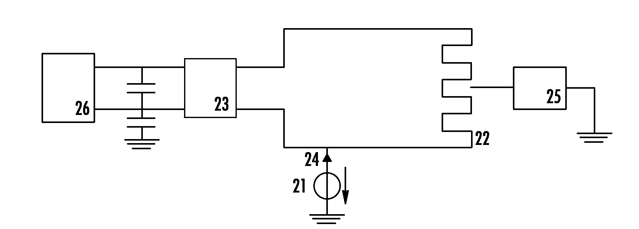
[0036]Referring to FIG. 1, which shows the basic structure of a capacitive occupancy sensing system:[0037]1 is the capacitive occupancy sensing system;[0038]2 is a control unit, e.g. a microcontroller;[0039]3...


PUM


Abstract

A plural-frequency capacitive occupancy sensing system comprises an antenna electrode and a detection circuit, which is configured to drive the antenna electrode at least with a first and a second signal at a first and a second frequency, respectively, so as to obtain at least a first and a second measurement value indicative of at least one of conductance, susceptance, resistance, reactance and capacitance between the antenna electrode and a reference node, at the first frequency and the second frequency, respectively. The detection circuit compares the capacitance between the antenna electrode and the reference node with a threshold capacitance, the threshold capacitance being derived from a difference between the first and second measurement values and / or the capacitance between the antenna electrode and the reference node being corrected based upon the difference between the measurement values. The detection circuit outputs an occupancy state signal depending on the comparison.

Description

TECHNICAL FIELD[0001]The present invention generally relates to a capacitive occupant detection system, e.g. for detecting the absence or presence of an occupant seated on a vehicle seat. A preferred embodiment of the invention relates to a combined seat heating and capacitively occupancy sensing device.BACKGROUND OF THE INVENTION[0002]A capacitive sensor, called by some electric field sensor or proximity sensor, designates a sensor, which generates a signal responsive to the influence of what is being sensed (a person, a part of a person's body, a pet, an object, etc.) upon an electric field. A capacitive sensor generally comprises at least one antenna electrode, which an oscillating electric signal is applied to and which thereupon emits an electric field into a region of space proximate to the antenna electrode, while the sensor is operating. The sensor comprises at least one sensing electrode at which the influence of an object or living being on the electric field is detected. ...

Claims


Application Information

Patent Timeline
Patent Type & Authority Patents(United States)
IPC IPC(8): G01R27/26G01R19/00B60N2/00B60N2/56B60R21/015
CPCB60N2/002B60N2/5685B60R21/01532
Inventor VIRNICH, MICHAELHOYER, DAVIDTHINNES, MARTINPUETZ, MICHAELMEYERS, THOMAS
Owner IEE INT ELECTRONICS & ENG SA
Why Eureka
Try Eureka