
Sheet conveying device

a conveying device and sheet technology, applied in the direction of thin material processing, article separation, printing, etc., can solve the problems of physical limitation of the distance between the printing portion and the nip portion, poor image formation, etc., to reduce or absorb load (impact), prevent variances in the amount of sheet feeding, and reduce the effect of absorbing load

Active Publication Date: 2007-05-01
BROTHER KOGYO KK
View PDF36 Cites 8 Cited by
  • Summary
  • Abstract
  • Description
  • Claims
  • Application Information

AI Technical Summary

Benefits of technology

[0009]Accordingly, one aspect of the invention is to provide a sheet conveying device that prevents a poor image formation by prevent improper sheet feeding and by minimizing variances of sheet feeding amounts.
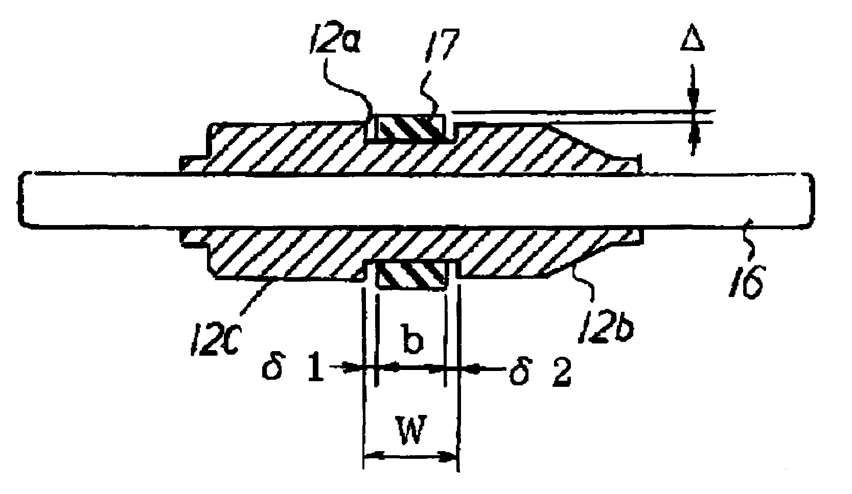
[0012]According to the invention, elastic deformation of the elastic ring fitted over the roller pair may reduce or absorb load (impact) that causes a rear end of the sheet to flick or spring and the improper sheet feeding, when the rear end of the sheet passes through the nip portion between the feed roller and the pinch roller. Thus, variances in the sheet feeding amounts and the poor image formation may be prevented.
[0013]When the feed roller and the pinch roller are reversely rotated for sheet registration, a leading end of the sheet may be prevented from contacting the elastic ring with the leading end being lifted, and the sheet may be favorably conveyed near the nip portion between the feed roller and the pinch roller, with the guide film. Therefore, poor sheet feeding such that the sheet end is turned up by the elastic ring while the feed roller and the pinch rollers are reversely rotated, may be prevented.

Problems solved by technology

However, reduction of the distance between the printing portion and the nip portion is physically limited.
This causes improper sheet feeding or variances in sheet feeding amounts, resulting in poor image formation.

Method used


Image

  • Sheet conveying device
  • Sheet conveying device
  • Sheet conveying device

Examples


Embodiment Construction

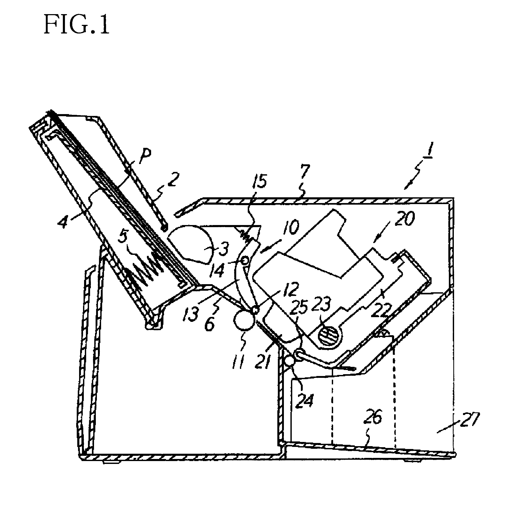
[0026]An ink jet printer 1 including a sheet conveying device 10 according to an embodiment of the invention will be described with reference to FIG. 1. As shown in FIG. 1, the ink jet printer 1 is provided at a rear side thereof (left side in FIG. 1) with a sheet feeder 2 capable of mounting a plurality of sheets P thereon. A pick-up roller 3 is disposed on a lower front side of the sheet feeder 2 at a position to contact the uppermost sheet P. The pick-up roller 3 is supported by a rotating shaft disposed along the width direction of the sheet P.

[0027]The sheet feeder 2 includes a tray 4 on which sheets P are mounted. The tray 4 is urged by a spring 5 toward the pick-up roller 3. Therefore, the uppermost sheet P on the tray 4 contacts the surface of the pick-up roller 3 by the urging force of the spring 5. The uppermost sheet P is separated by the pick-up roller 3 driven by a motor (not shown), and fed along a guide 6 in a sheet feeding direction (in a slanting downward direction)...


PUM

PropertyMeasurementUnit
widthaaaaaaaaaa
widthaaaaaaaaaa
friction coefficientaaaaaaaaaa

Abstract

A sheet conveying device includes a metal feed roller driven by a drive source and a plastic pinch roller pressed against the feed roller. A sheet is held between the feed roller and the pinch roller, to convey the sheet to a recording unit. An elastic ring having a high wear resistance is fitted over a part of an outer surface of the pinch roller in a width direction of the pinch roller. Accordingly, the elastic deformation of the elastic ring reduces or absorbs load (impact) that causes a rear end of the sheet to flick or spring and the improper sheet feeding, when the rear end of the sheet passes through a nip portion between the feed roller and the pinch roller. Thus, variances in the sheet feeding amounts and the poor image formation are prevented.

Description

BACKGROUND OF THE INVENTION[0001]1. Field of Invention[0002]The invention relates to a sheet conveying device, for use in an image forming apparatus, that conveys sheets to a recording unit, by holding the sheets between a feed roller and a pinch roller.[0003]2. Description of Related Art[0004]Printing devices, such as ink jet printers, are provided with sheet conveying devices for conveying sheets mounted on a sheet cassette one by one to a recording or printing unit. The sheet conveying device includes a metal feed roller that is driven by a drive source to rotate, and a plastic pinch roller pressed against the feed roller. The sheet is held between the feed roller and the pinch roller and conveyed to the recording unit.[0005]To increase a printing accuracy of the printing devices, an accuracy of a sheet conveyance with the sheet conveying device needs to be increased. Especially, the ink jet printers that perform printing in high dot density, require the higher sheet conveying ac...

Claims


Application Information

Patent Timeline
Patent Type & Authority Patents(United States)
IPC IPC(8): B65H3/06B41J13/10B41J13/076B65H5/06B65H5/38
CPCB65H5/062B65H2401/115B65H2404/1312B65H2404/1316B65H2404/133B65H2404/143B65H2404/144B65H2401/11
Inventor DESHIMARU, TERUOHIGUCHI, TOMOHISA
Owner BROTHER KOGYO KK
Learn More