Multi-planar adjustable connector

a multi-planar adjustable and connector technology, applied in the field of multi-planar adjustable connectors, can solve the problems of difficult connection between the spinal support rod and the vertebral anchorage, and the system, however, has no elevation adjustment capability afterward

Inactive Publication Date: 2007-05-01
WARSAW ORTHOPEDIC INC
View PDF4 Cites 129 Cited by
  • Summary
  • Abstract
  • Description
  • Claims
  • Application Information

AI Technical Summary

Problems solved by technology

It is difficult to provide secure connections between the spinal support rod and these vertebral anchors at all the various angles and elevations that are required, especially where there are different distances between the rod and bolts and where these components are located at different heights on the patient.
This system, however, has no elevation adjustment capability after the bone anchor is installed because the clamp in that invention must be secured between a nut and an immovable shoulder on the bone anchor.

Method used


Image

  • Multi-planar adjustable connector
  • Multi-planar adjustable connector
  • Multi-planar adjustable connector

Examples


Embodiment Construction

[0018]specific language is used in the following description to publicly disclose the invention and to convey its principles to others. No limits on the breadth of the patent rights based simply on using specific language are intended. Also included are any alterations and modifications to the description that should normally occur to one of average skill in this technology.

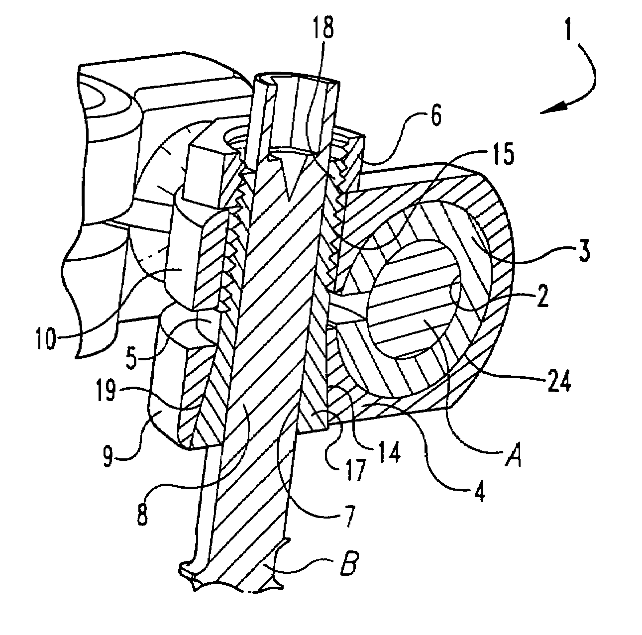
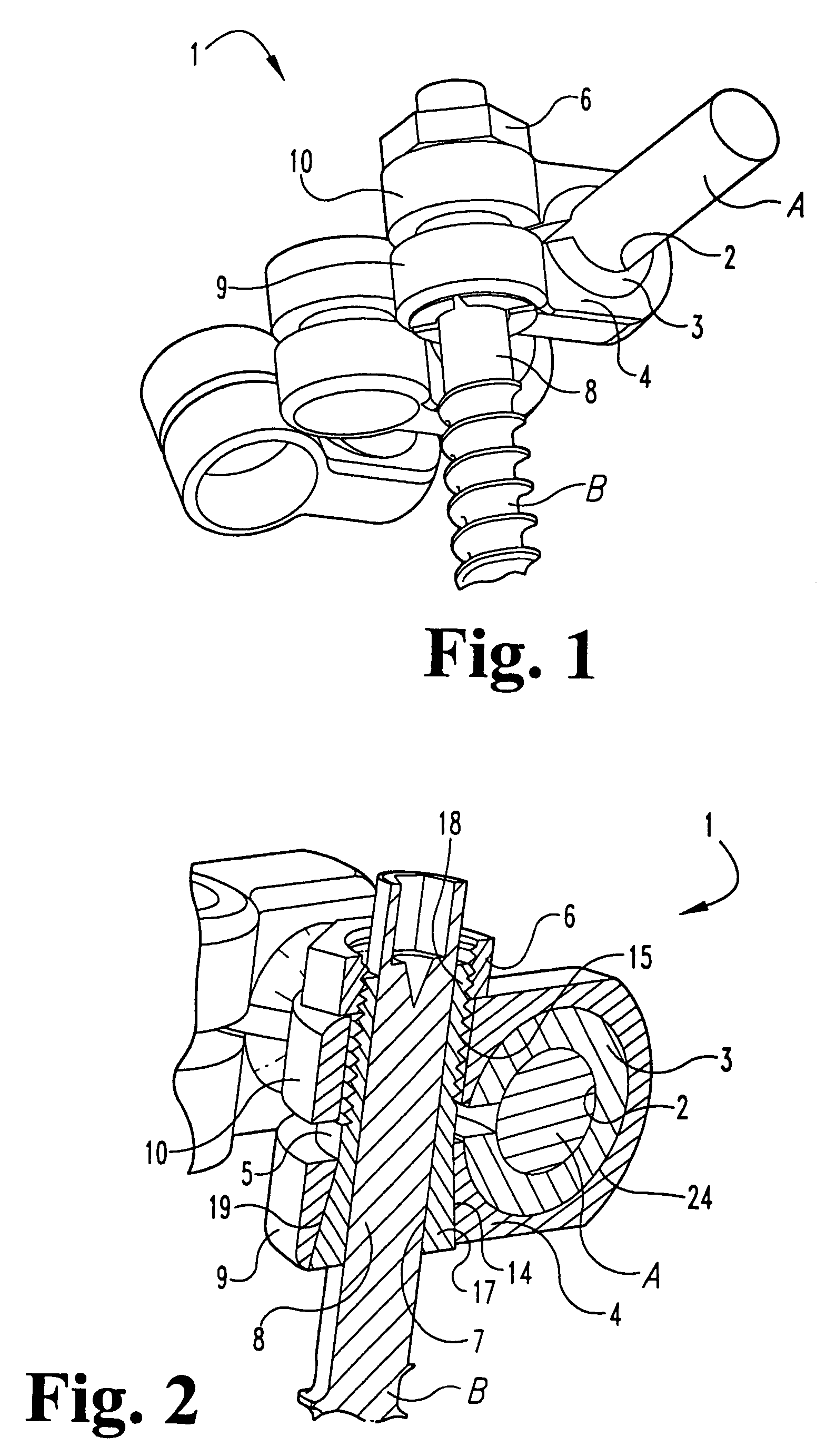
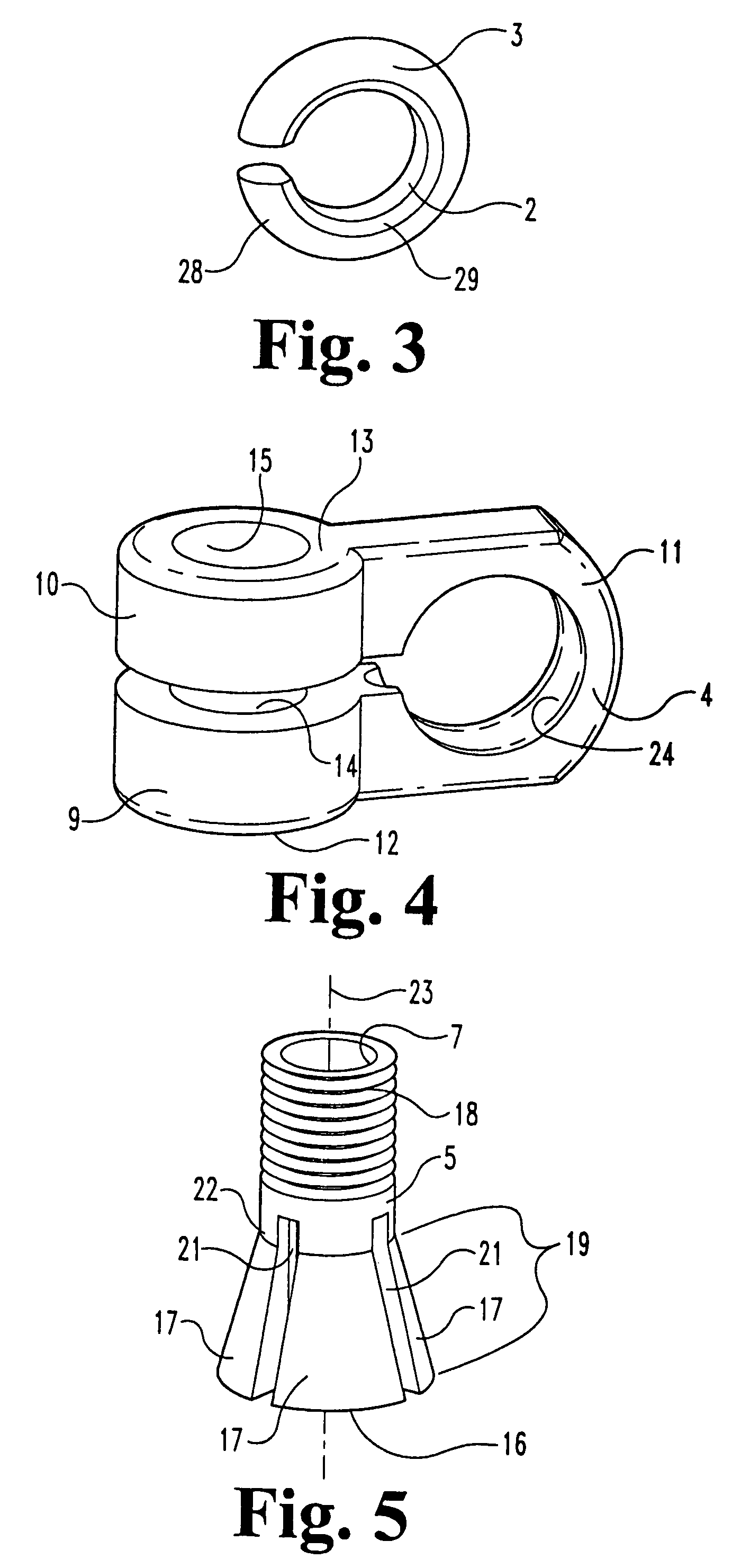
[0019]A connection assembly 1 according to one embodiment of the invention is shown in FIGS. 1 and 2. Connection assembly 1 includes a compressible ring or split ring 3, a shackle or clamp 4, a collet 5, and a nut 6. Compressible ring 3 has an aperture 2 for receiving a rod “A” in a spinal implant system and collet 5 has a socket 7 for receiving the shank or post 8 of a vertebral anchor “B”. As shown, socket 7 is preferably open between the top and bottom of the connection assembly to allow post or shank 8 to extend through collet 5 so that collet 5 can be locked into place anywhere along the length of shank 8.

[0...


PUM


Abstract

A connection assembly between a spinal implant rod and a vertebral anchor. The assembly has a split ring, a clamp, a collet and optionally a nut. The split ring is located inside the clamp and the collet is inserted through each of the clamp's arms. In use, the spinal implant rod is placed inside the split ring and the shaft or shank of the vertebral anchor is placed inside the collet. Drawing the arms of the clamp together then tightens the connection assembly, which closes the collet around the vertebral anchor and closes the split ring around the implant rod. Threading a nut on one end of the collet or directly threading the collet into one of the arms of the clamp tightens the assembly.

Description

[0001]This application is a continuation of U.S. patent application Ser. No. 09 / 694,228, filed Oct. 23, 2000 (new issued as U.S. Pat. No. 6,626,906) which is incorporated herein by reference.[0002]This invention relates to a laterally adjustable connection between a spinal rod and a vertebral anchor, and more particularly relates to a spinal implant connection that is dorsally adjustable.BACKGROUND OF THE INVENTION[0003]spinal implant systems provide a rod for supporting the spine and for properly positioning components of the spine for various treatment purposes. Bolts, screws, and hooks are typically secured to the vertebrae for connection to the supporting rod. These vertebral anchors must frequently be positioned at various angles due the anatomical structure of the patient, the physiological problem being treated, and the preference of the physician. It is difficult to provide secure connections between the spinal support rod and these vertebral anchors at all the various angle...

Claims


Application Information

Patent Timeline
Patent Type & Authority Patents(United States)
IPC IPC(8): A61B17/56A61B17/58A61B17/00A61B18/04A61B17/70
CPCA61B17/7037A61B17/7041A61B17/704A61B2017/00858
Inventor YOUNG, STUART
Owner WARSAW ORTHOPEDIC INC
Why Eureka
Try Eureka