Downhole Tool with Collapsible or Expandable Split Ring

a technology of split rings and tools, which is applied in the direction of fluid removal, borehole/well accessories, construction, etc., can solve the problems of limiting the number of valves that can be used and the upper limit on the total available plug sizes

Inactive Publication Date: 2015-06-18
PEAK COMPLETION TECH
View PDF2 Cites 39 Cited by
  • Summary
  • Abstract
  • Description
  • Claims
  • Application Information

AI Technical Summary

Problems solved by technology

Thus, these traditional valve assemblies limit the number of valves that can be used in a given tubing string because each ball size is only able to actuate a single valve.
Certain seat assemblies may allow plug increments of 0.0625 inches, which provides more available seats, but still creates an upper limit on the total available plug sizes.

Method used


Image

  • Downhole Tool with Collapsible or Expandable Split Ring
  • Downhole Tool with Collapsible or Expandable Split Ring
  • Downhole Tool with Collapsible or Expandable Split Ring

Examples


Embodiment Construction

[0029]When used with reference to the figures, unless otherwise specified, the terms “upwell,”“above,”“top,”“upper,”“downwell,”“below,”“bottom,”“lower,” and like terms are used relative to the direction of normal production and / or flow of fluids and or gas through the tool and wellbore. Thus, normal production results in migration through the wellbore and production string from the downwell to upwell direction without regard to whether the tubing string is disposed in a vertical wellbore, a horizontal wellbore, or some combination of both. Similarly, during treatment of a well, which may include a fracturing, or “fracing,” process, fluids move from the surface in the downwell direction to the portion of the tubing string within the formation to be treated.

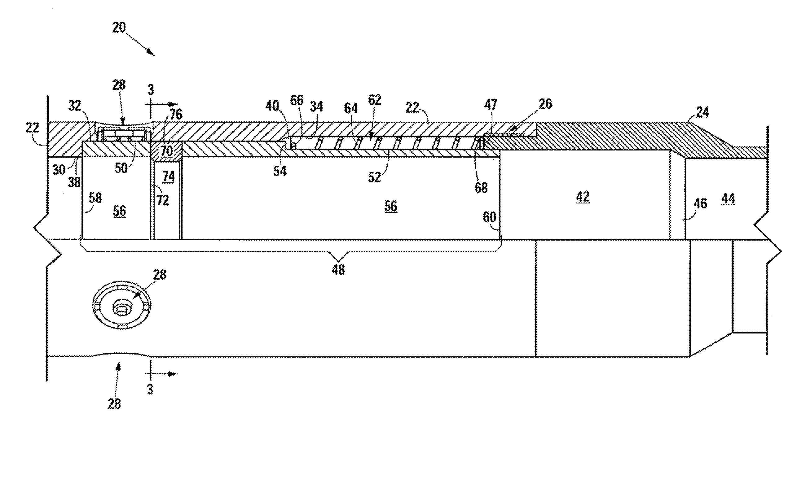
[0030]FIG. 1 shows an embodiment tool 20, which comprises a housing 22 connected to a bottom connection 24 at a threaded section 26. The housing 22 has a plurality of radially-oriented, circumferentially-aligned ports 28 providing ...


PUM


Abstract

A valve assembly, and related system and method, with a sleeve having an inner surface with a diameter, an outer surface, and a plurality of openings extending between the inner surface and the outer surface. A split ring having one or more segments and an expandable or collapsible body with a seating surface and an outer diameter extending from the body is at least partially within the inner surface of the sleeve. The split ring and sleeve may be placed in a variable diameter housing such that contact of the outer diameter with a smaller diameter section of the housing causes the split ring to close, whereas contact with an larger diameter of the housing allows the split ring to open. In certain embodiments, a spring element, which may be the split ring itself, applies force to move the split ring from an open to closed position. A spring may be positioned around a portion of the sleeve and in an annular space at least partially defined by an annular body and the second cylindrical outer surface.

Description

CROSS-REFERENCES TO RELATED APPLICATIONS[0001]This application claims the benefit of U.S. Provisional Patent Application Ser. No. 61 / 868,867, filed on Aug. 22, 2013 and entitled “Downhole Tool with Collapsible or Expandable Split Ring”; is a Continuation in Part, and claims the benefit, of U.S. patent application Ser. No. 13 / 423,158, filed Mar. 16, 2011 entitled “Multistage Production System Incorporating Valve assembly With Collapsible or Expandable C-Ring,” which claims the benefit of U.S. Provisional Patent Application Ser. No. 61 / 453,288 and U.S. patent application Ser. No. 13 / 448,284 , entitled “Assembly for Actuating a Downhole Tool” filed on Apr. 16, 2012, which claims the benefit of U.S. Provisional Application 61 / 475,333 filed Apr. 14, 2011 entitled “Valve Assembly and System for Producing Hydrocarbons”, each of which is incorporated by reference herein.STATEMENT REGARDING FEDERALLY-SPONSORED RESEARCH OR DEVELOPMENT[0002]Not applicable.BACKGROUND OF THE INVENTION[0003]1. Fi...

Claims


Application Information

Patent Timeline
Patent Type & Authority Applications(United States)
IPC IPC(8): E21B34/16
CPCE21B2034/007E21B34/16E21B34/14E21B43/26E21B2200/06E21B34/142
Inventor HOFMAN, RAYMONDMUSCROFT, WILLIAM SLOANE
Owner PEAK COMPLETION TECH
Why Eureka
Try Eureka