Multi-Purpose Well Servicing Apparatus

a multi-purpose, well-maintained technology, applied in mechanical equipment, wellbore/well accessories, drilling pipes, etc., can solve the problems of high cost, difficult to change scraper blades/brushes, and limitations of known prior art tools

Inactive Publication Date: 2010-07-22
HALLIBURTON ENERGY SERVICES INC
View PDF74 Cites 39 Cited by
  • Summary
  • Abstract
  • Description
  • Claims
  • Application Information

AI Technical Summary

Problems solved by technology

As a result, the known prior art tools have certain limitations, inc

Method used


Image

  • Multi-Purpose Well Servicing Apparatus
  • Multi-Purpose Well Servicing Apparatus
  • Multi-Purpose Well Servicing Apparatus

Examples


Embodiment Construction

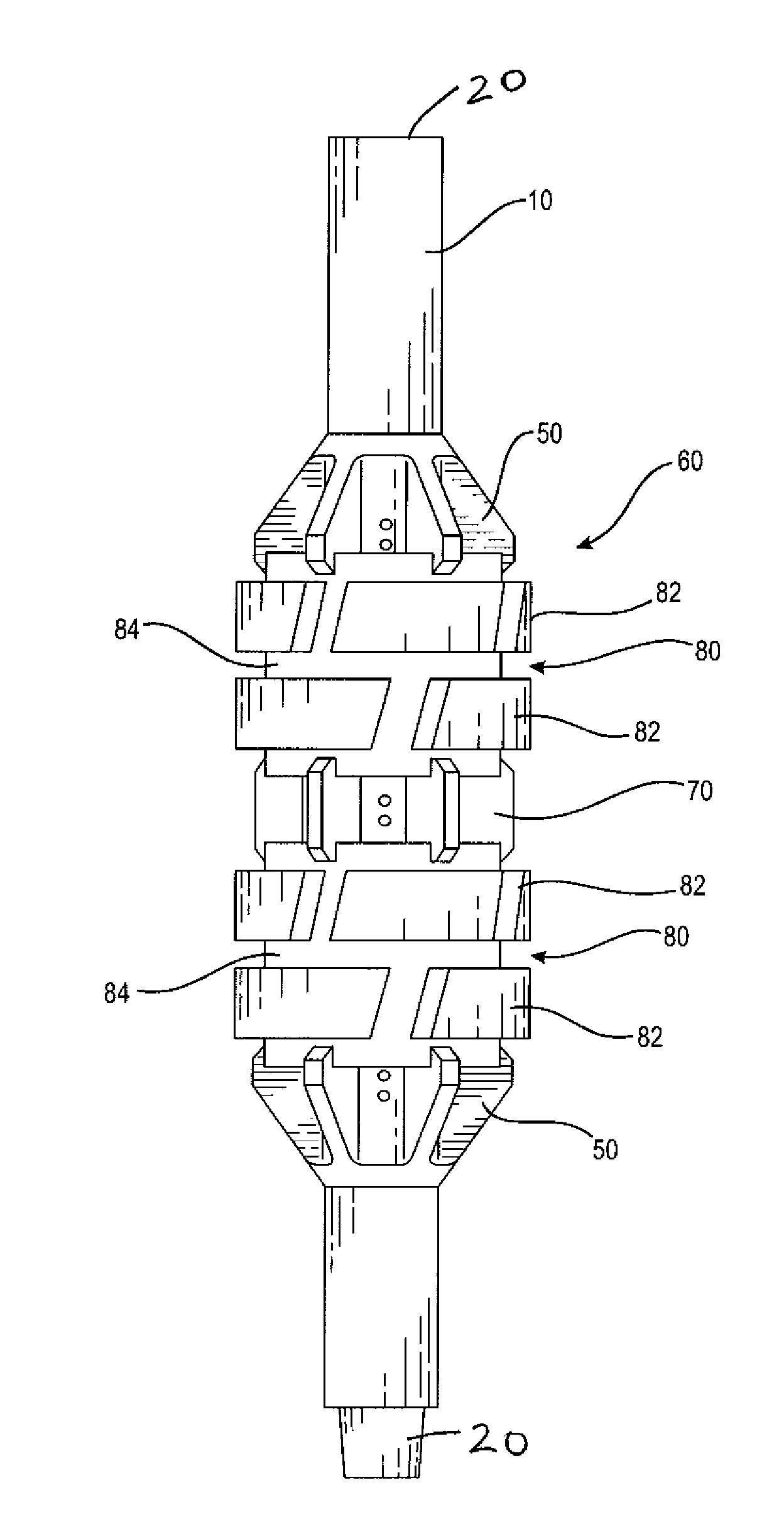
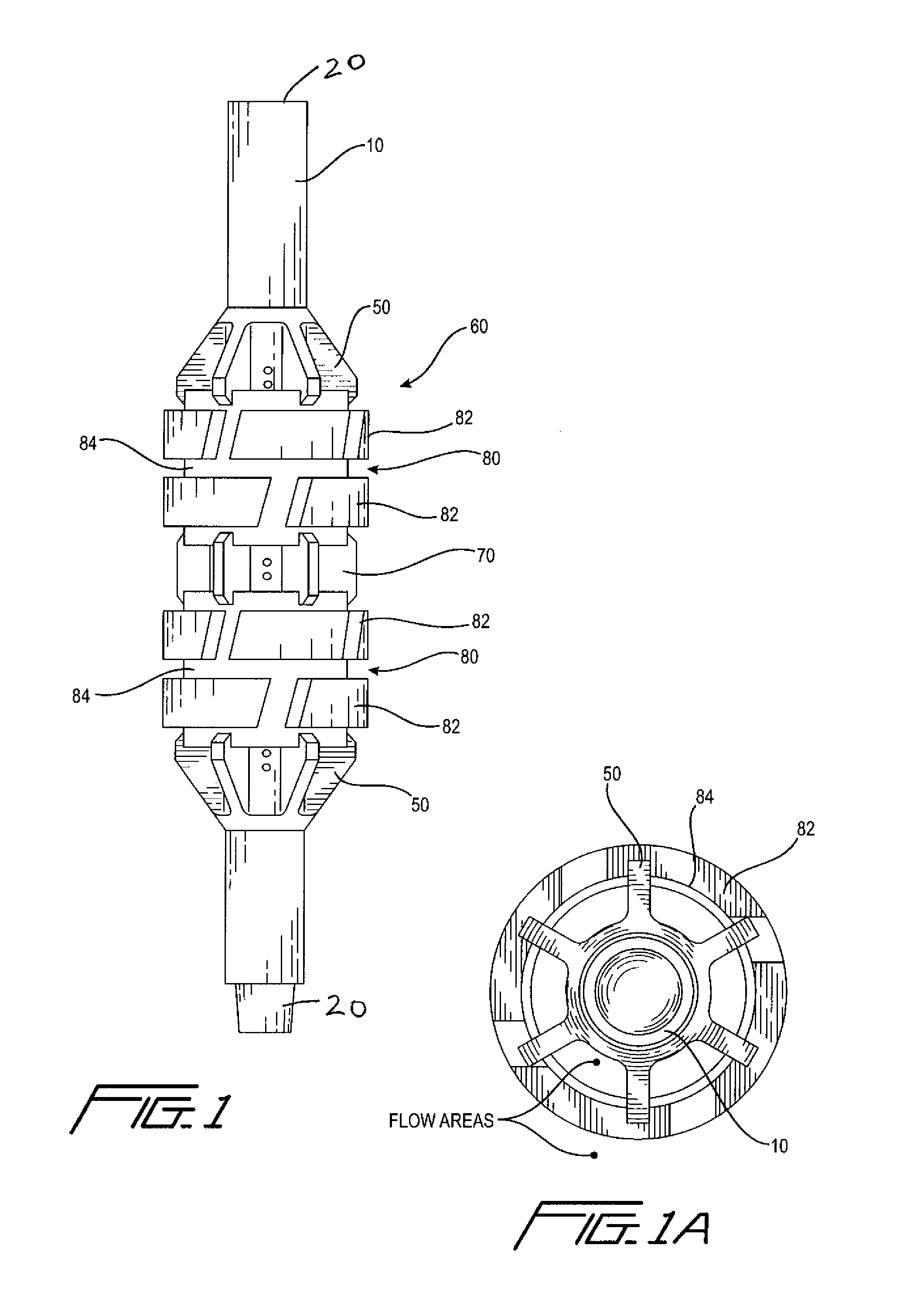
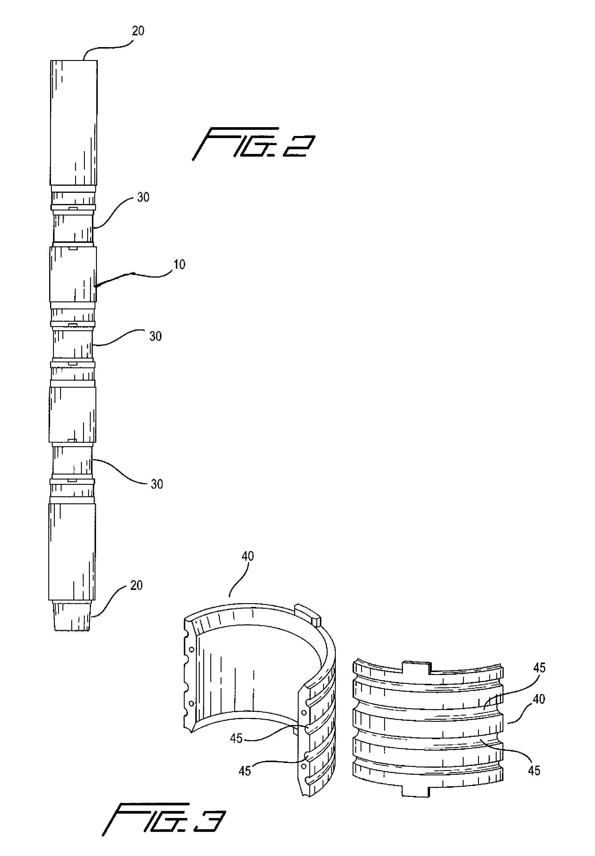
[0022]Various embodiments of the present invention comprise enhanced and improved downhole tool assemblies, for cleaning the internal wall of tubulars (casing, risers, etc.) and the collection of the material being cleaned. Generally, a downhole tool comprising the present invention is connected to a string of drill pipe, work string, tubing, or the like, referred to collectively as a “drill string,” to be run into a wellbore tubular, and used in the servicing of oil and gas wells. For this application, the term “wellbore” includes without limitation any downhole tubular, whether a casing string, a riser associated with a floating drilling rig or any other type rig, or any other tubular member. In an exemplary embodiment, the apparatus of the present invention comprises two primary elements:[0023]1) a central mandrel, typically connected by a threaded connection to a drill string, comprising an outer diameter profile (such as under-cut profiles or other outer diameter variations) wh...


PUM


Abstract

Apparatus for cleaning the inner wall of wellbore tubulars, and for capturing downhole debris in the wellbore An elongated, tubular central mandrel has threaded connections on either end for makeup into a tubular string The mandrel has recesses on its outer circumference into which split rings are mounted Various service elements are then attachable to the central mandrel, by sliding them over the mandrel and holding them in place with stabilizer elements which connect to the split rings Different embodiments of the service elements include a brush assembly, a junk basket, and a magnet The stabilizer elements may be mounted onto the split rings so as to either be rotationally locked with respect to the mandrel, or so as to be capable of rotating with respect to the mandrel, since the service elements are held in place on the central mandrel by the stabilizer elements.

Description

CROSS REFERENCE TO RELATED APPLICATIONS[0001]This regular patent application claims priority to U.S. provisional patent application Ser. No. 60 / 958,507, filed Jul. 6, 2007, for all purposes.BACKGROUND [0002]1. Field of the Invention[0003]This invention relates to tools used in the drilling and servicing of oil and gas wells, referred to hereinafter as “wells.” More particularly, this invention generally relates to a downhole (that is, to be run from the surface down into a well) tool comprising interchangeable service components, which are retained on the outer diameter of a central mandrel. The invention can be used to clean the inner walls of casing, risers (e.g. on a floating drilling rig), or any like surfaces, or to collect solid contaminants generally present in these sections either on inner walls, or within the wellbore fluid itself. The interchangeable components are interchangeable in various configurations, and mounted on the mandrel so as to be either rotational or non-r...

Claims


Application Information

Patent Timeline
IPC IPC(8): E21B37/00E21B17/10E21B37/02E21B31/06E21B31/08
CPCE21B27/00E21B37/02E21B17/1057E21B31/06F16C2352/00F16C19/08F16C33/60E21B37/00E21B31/08
Inventor KNOBLOCH, BENTONROY, TODD
Owner HALLIBURTON ENERGY SERVICES INC
Why Eureka
Try Eureka