

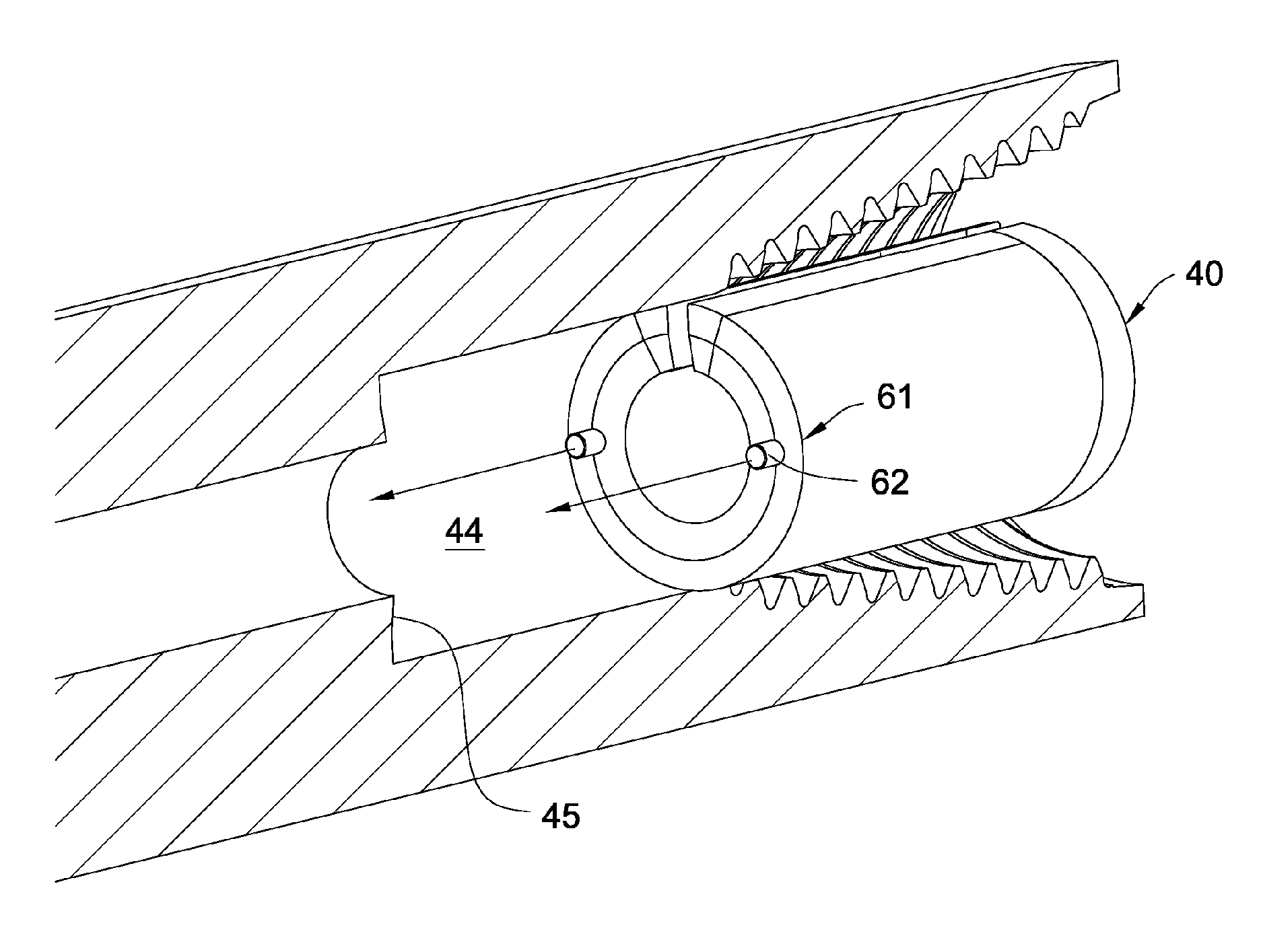
Hanger mounted in the bore of a tubular component
a tubular component and hanger technology, applied in the direction of connecting contact material, rod connection, coupling, etc., can solve the problem that the interface between the hanger and the bore may also be non-uniform
- Summary
- Abstract
- Description
- Claims
- Application Information
AI Technical Summary
Benefits of technology
Problems solved by technology
Method used
Image

Examples
Embodiment Construction
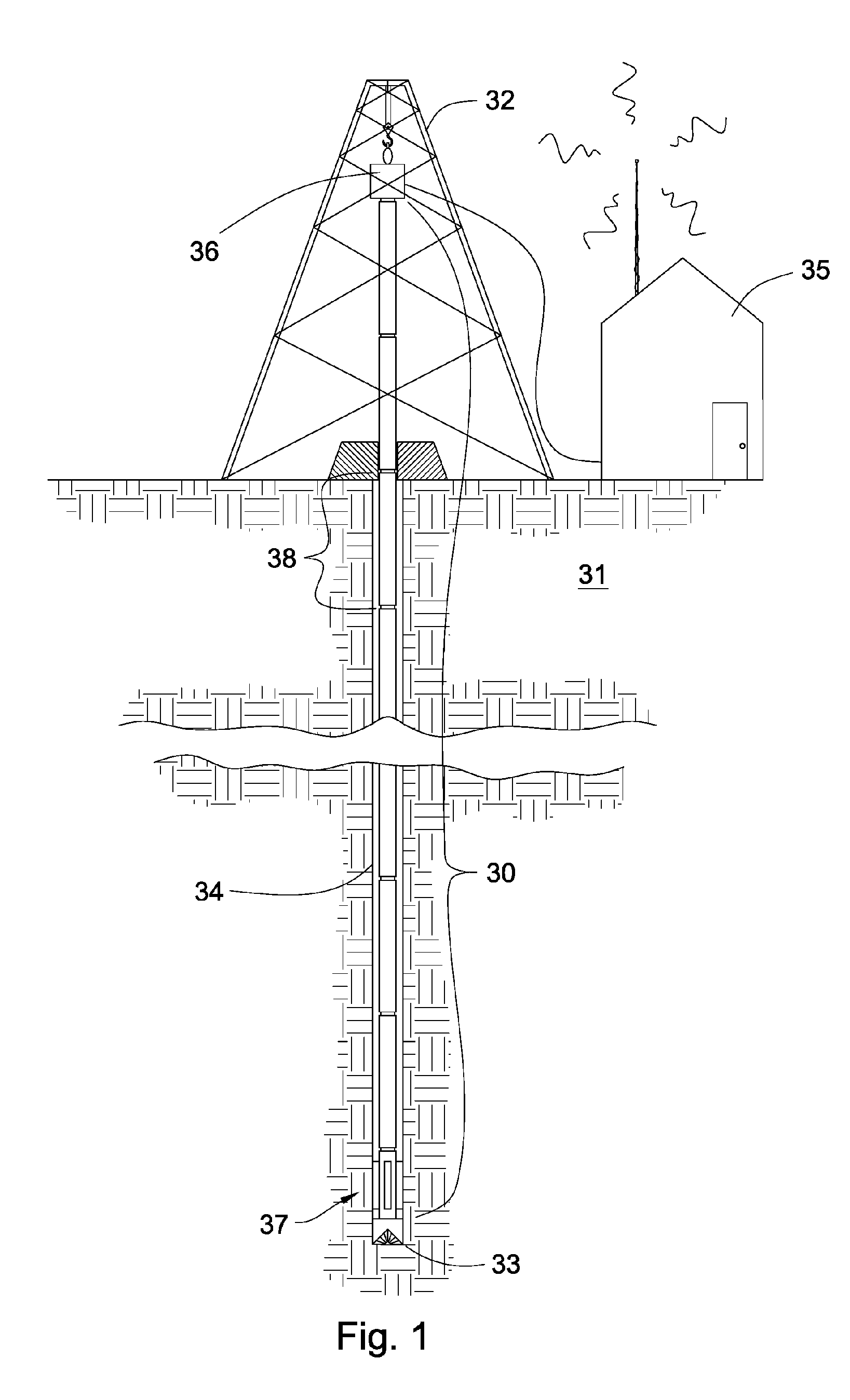
[0034]FIG. 1 is a perspective diagram of a downhole tool string 30 suspended in the earth 31. A derrick 32 supports the tool string 30. The tool string 30 may be made up of a plurality of tubular components 38. The tubular components 38 may be production pipe, drill pipe, single shouldered pipe, double shouldered pipe, drill collars, heavy weight pipe, reamers, motors, composite pipe, subs, swivels, jars, hammers, shock absorbers, or downhole equipment 37 such as may be included in bottom hole assemblies. Downhole tools, such as those located near the bottom 33 of the borehole 34, may communicate with surface equipment 35 through a downhole telemetry system. A swivel connection 36 may transmit data, power, network packets, or combinations thereof between the tool string 30 and the surface equipment 35. Alternatively, a wireless transceiver may be used to communicate between the surface equipment and the downhole equipment.
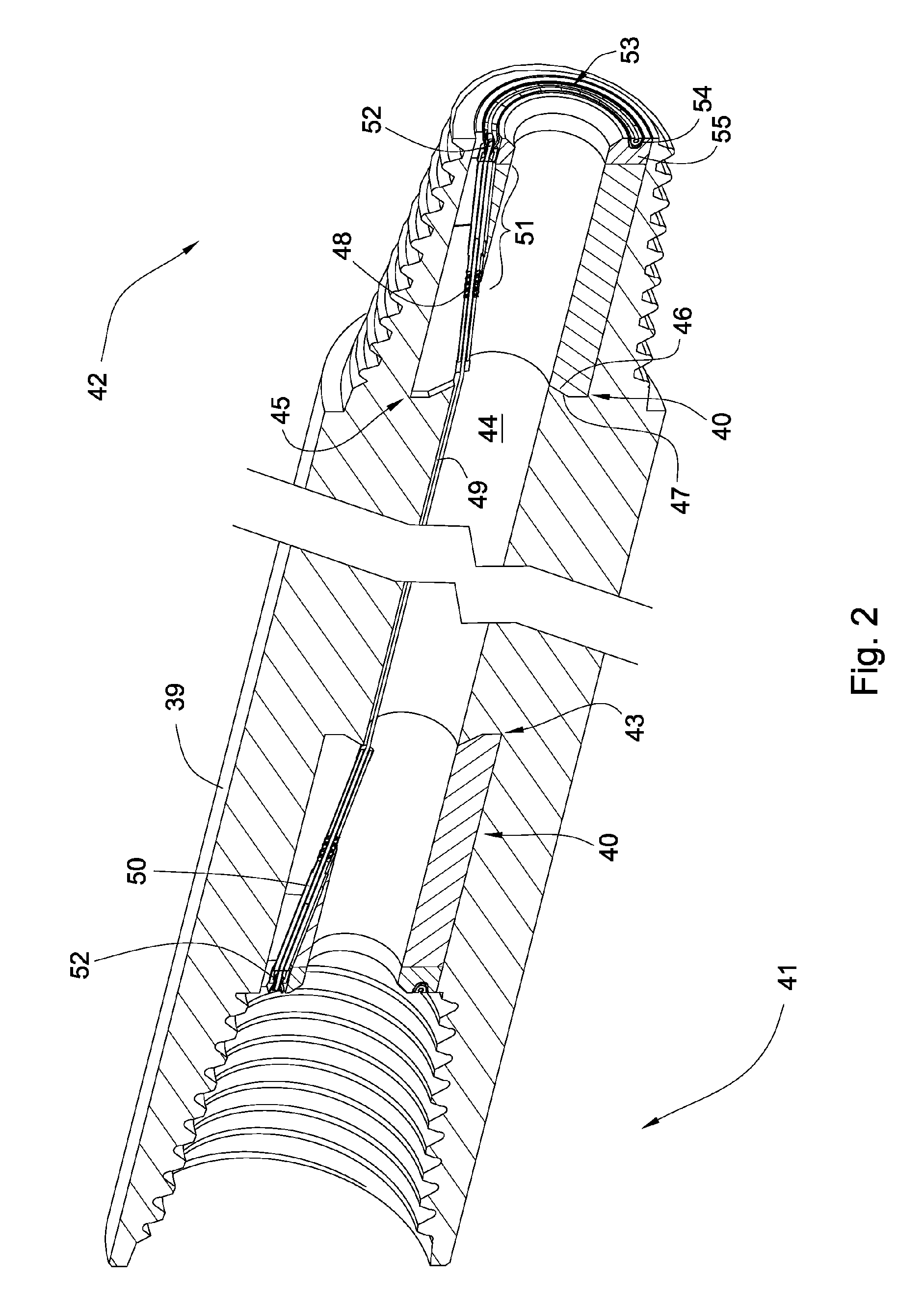
[0035]FIG. 2 is a perspective cross sectional diagram of a dr...
PUM
 Abstract
Description
Claims
Application Information