Vane radial mounting apparatus

Inactive Publication Date: 2005-01-18
HONEYWELL INT INC
View PDF24 Cites 42 Cited by
  • Summary
  • Abstract
  • Description
  • Claims
  • Application Information

AI Technical Summary

Benefits of technology

In another aspect of the invention, slots in the shroud can be used to provide installation clearance for the blade of the vane. These small slots allow the vanes to be manually pushed to a radial position beyond what would otherwise be possible to provide maximum radial clearance during installation of the vane and shroud assembly. Vane to shroud assembly can occur outside the engine with all the vanes stil

Problems solved by technology

Using a split ring housing increases manufacturing costs because the two rings must be machined and maintained as a matched set.
Making a separate locating ring requires making an additional, often flimsy part that can be difficult to hold in place and has holes with close tolerances ma

Method used


Image

  • Vane radial mounting apparatus
  • Vane radial mounting apparatus
  • Vane radial mounting apparatus

Examples


Embodiment Construction

The following detailed description is of the best currently contemplated modes of carrying out the invention. The description is not to be taken in a limiting sense, but is made merely for the purpose of illustrating the general principles of the invention, since the scope of the invention is best defined by the appended claims.

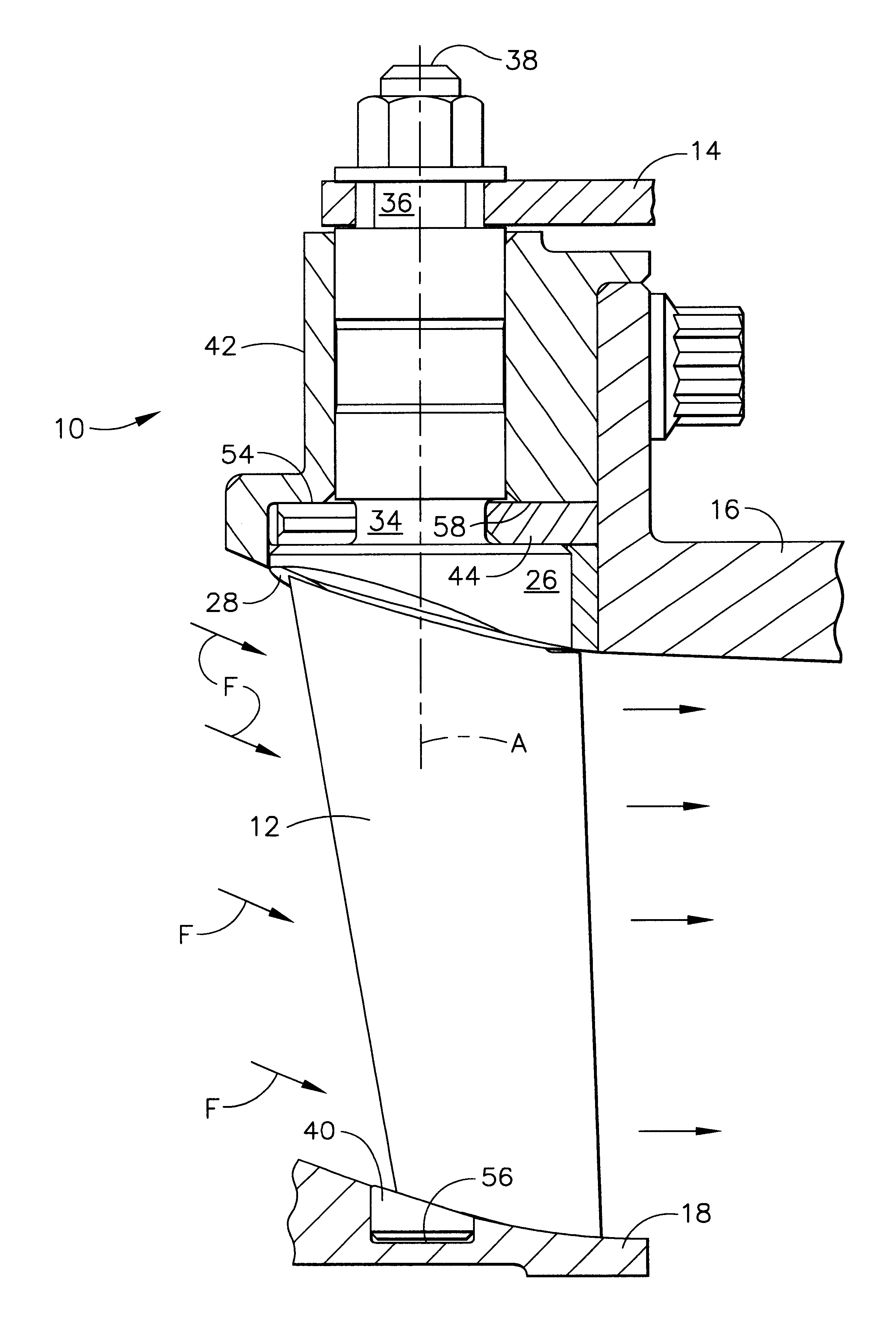
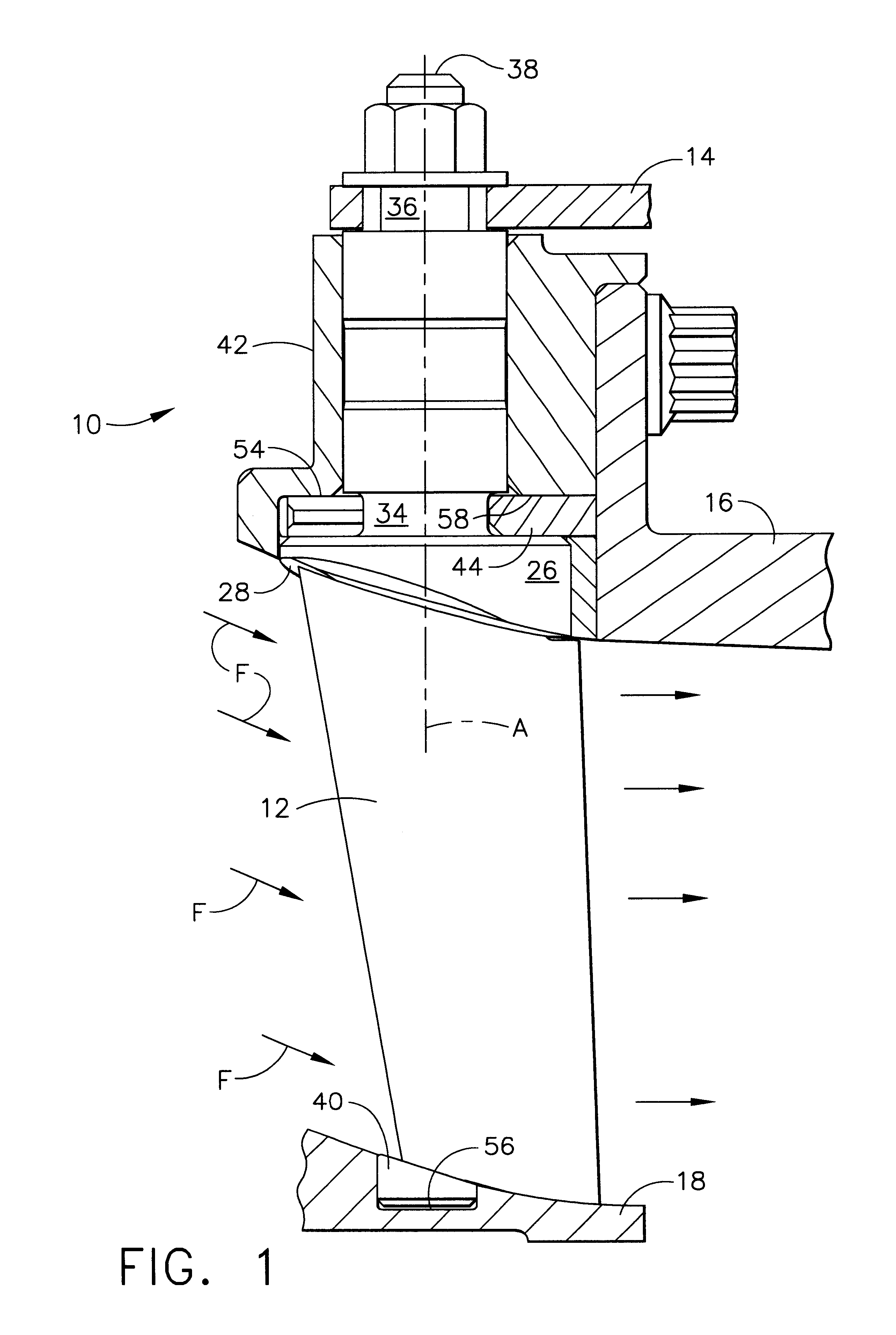
FIG. 1 shows a partial cross section of a portion of a turbine engine such as might be used in a commercial airliner and other applications. The stator assembly 10 uses an improved variable geometry vane 12 that, unlike the prior art, does not include threaded connectors that can become loose. The variable geometry vane 12 is shown in the intake air stream indicated by arrows ‘F’. The turbine engine stator assembly 10 may include a linkage arm 14 that controls the angle of attack of the variable geometry vane 12 and thus the intake air stream indicated by arrows ‘F’ through the stator assembly 10. It will be understood that while only one vane 12 is shown, a ...


PUM


Abstract

A variable geometry vane for use in a turbine engine. The vane can be radially mounted in a shroud ring while outside the turbine engine. The shroud and vane assembly can then be mounted to an engine hub without disassembly of the shroud, eliminating the need for a split ring shroud. Once located surrounding the hub, vanes are slid radially inward until a radially inward vane button engages a hole within the hub. Vanes are locked in place using clips slid into slots within the shroud. The clips are retained in place using an adjacent engine part bolted to the face of the shroud. Once in place within the engine, vanes are attached to a control arm for airflow adjustment.

Description

BACKGROUND OF THE INVENTIONIn turbine engine construction it is common to use a stator to control and direct the flow of air within the compressor of the turbine engine. Radial vanes are commonly used to direct the flow. The vanes have a blade like shape and are typically attached at one end to an external housing and can be attached at the other end to an internal hub. The vanes generally have a radial orientation. Variable vanes include a control mechanism that rotates the vanes about their radial axis to control the direction and amount of airflow into downstream parts of the engine.Variable geometry or static guide vanes, especially those having a locating button on the unshafted end, normally require a split ring housing, a separate locating ring, axial clearance grooves or a combination of these features in order to assemble the vane pattern. The requirement for these assembly methods in prior art devices is based on the fact that some form of axial motion is required to assem...

Claims


Application Information

Patent Timeline
IPC IPC(8): F01D17/16F01D17/00
CPCF01D17/162F05D2230/64F05D2230/60
Inventor HIDALGO, MARIO A.ALLAN, ADRIAN R.CRUSE, LOUIS D.
Owner HONEYWELL INT INC
Why Eureka
Try Eureka