Monitoring changeable locations of client devices in wireless networks

a wireless network and client device technology, applied in transmission monitoring, surveillance circuits, instruments, etc., can solve the problems of not understanding the side effects of its use and no insight into the underlying technology, and achieve the effect of improving security in wifi networks

Inactive Publication Date: 2007-05-01
INT BUSINESS MASCH CORP
View PDF15 Cites 42 Cited by
  • Summary
  • Abstract
  • Description
  • Claims
  • Application Information

AI Technical Summary

Benefits of technology

[0010]An object of the present invention is to improve security in WiFi networks.
[0012]A further object of the present invention is to provide improvements to WiFi networks that are easy to set up, even in a home environment, and that do not require changes to the WiFi standards or to existing client device adapters.
[0014]A further object of the present invention is to provide techniques for deterring and / or detecting theft of wireless devices.

Problems solved by technology

As the majority of users purchasing commodity-priced WiFi gear are non-technical, they have no insight to the underlying technology nor do they understand the side effects of its use.
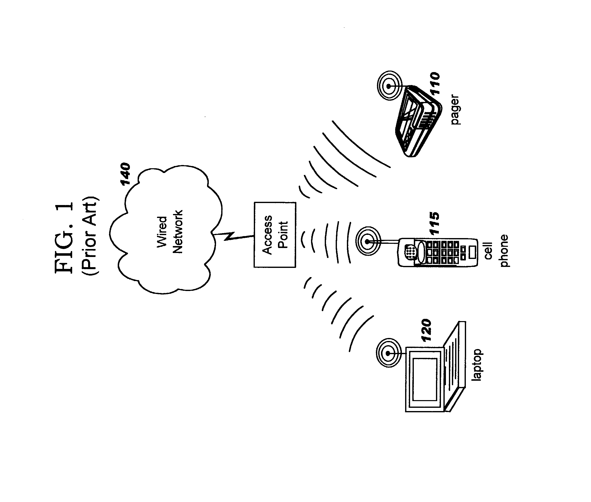
Unfortunately, WiFi has also attracted the hacker fringe, who view its deployment as an invitation to steal access to the Internet and / or locally-available services.

Method used


Image

  • Monitoring changeable locations of client devices in wireless networks
  • Monitoring changeable locations of client devices in wireless networks
  • Monitoring changeable locations of client devices in wireless networks

Examples


Embodiment Construction

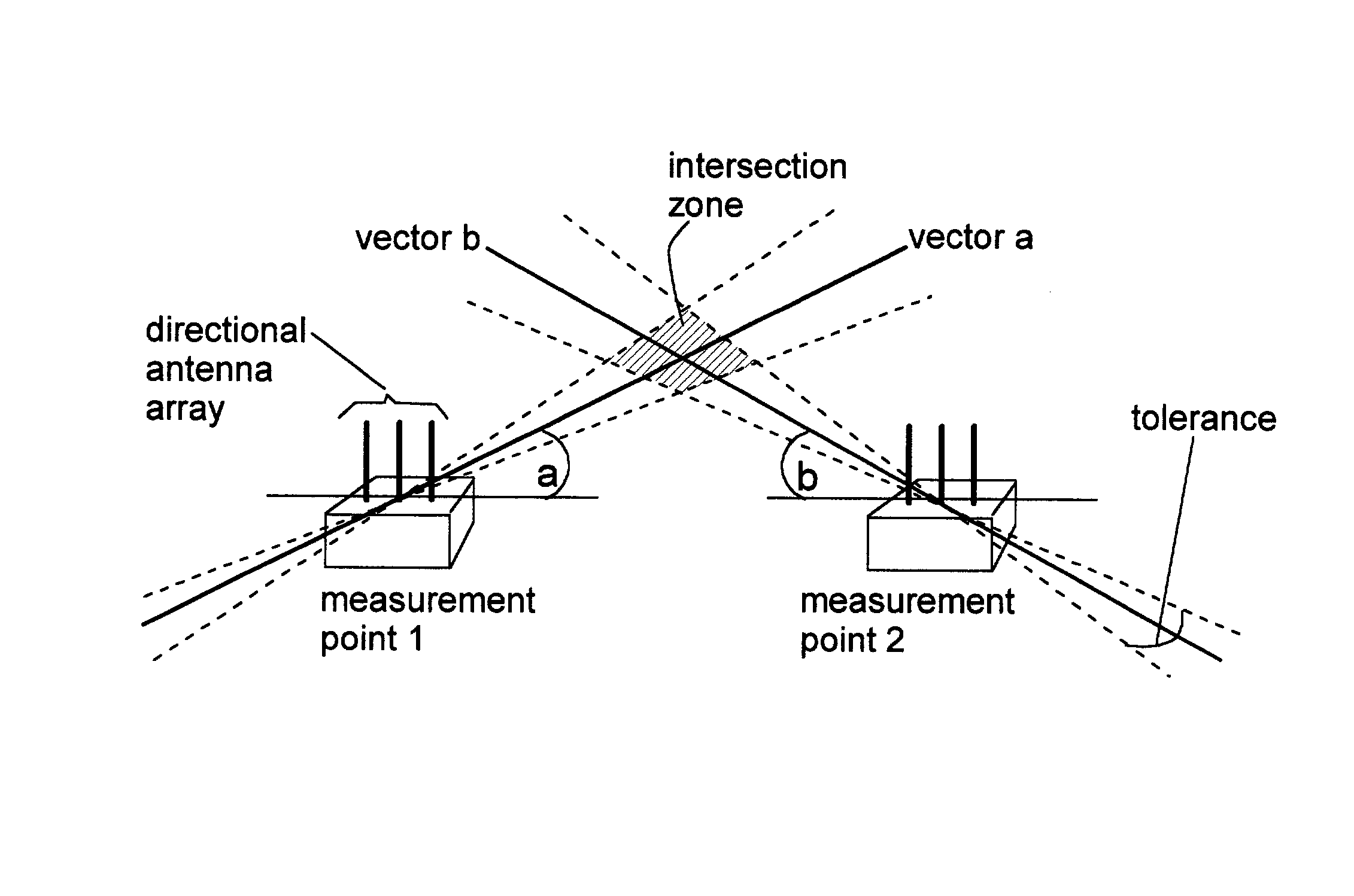
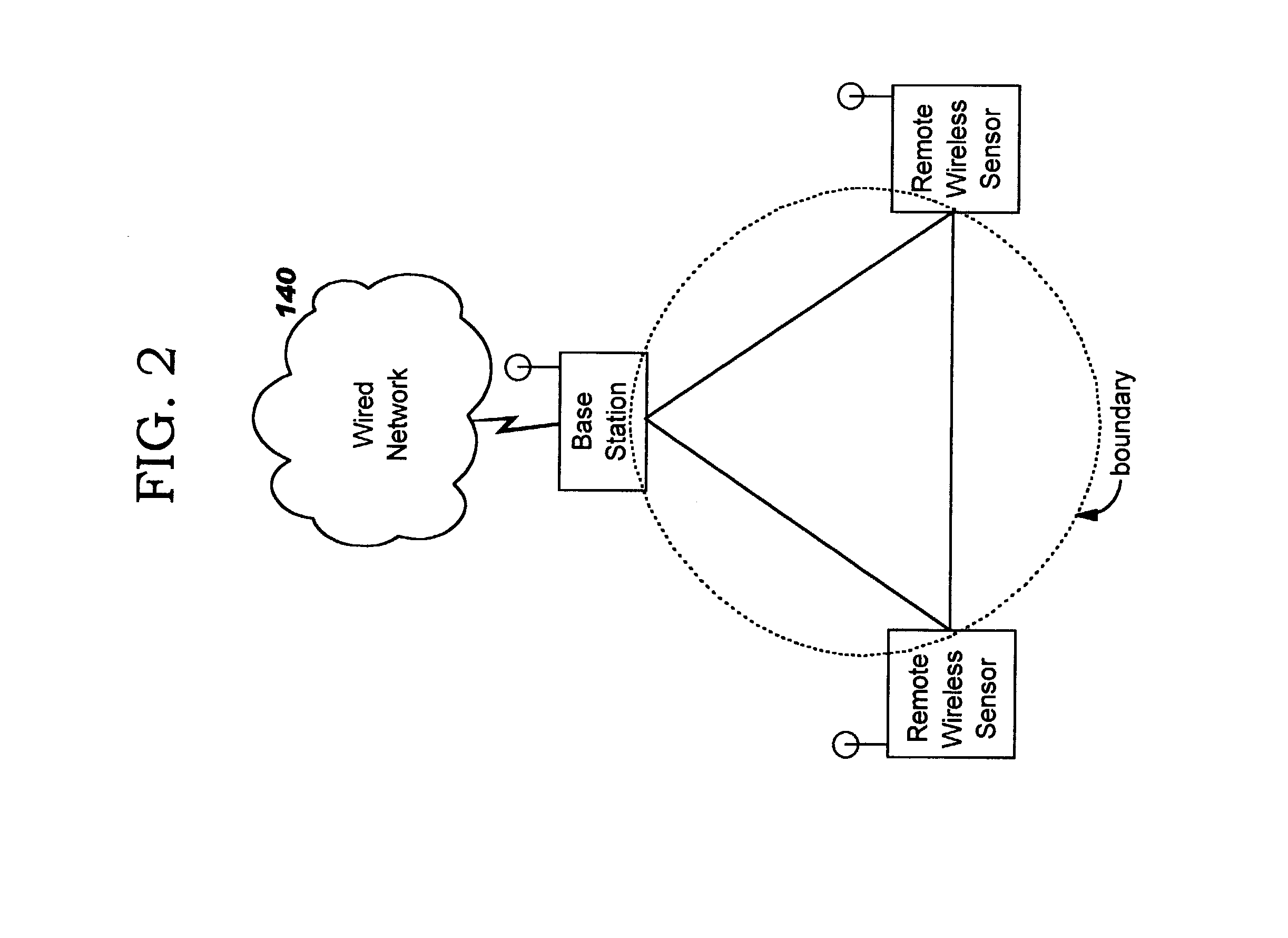
[0028]Security of wireless networks is improved by rejecting traffic from a wireless device located outside a defined spatial boundary. The device's spatial position with respect to the boundary is determined using multiple directional antenna arrays and calculating where the vectors intersect. Problems of prior art approaches are solved by the present invention, which provides a novel application of existing technologies.

[0029]Most client adapters in existing devices use omni-directional antennas. However, in addition to the significant attenuation of the radio signal as it passes through intervening objects like walls and furniture, these so-called omni-directional antennas exhibit significant variations in gain patterns, i.e., they are not really omni-directional. Thus, the signal strength seen at a receiver is of no use in determining the distance to the transmitter.

[0030]The present invention overcomes problems of the prior art using a modified WiFi access point (also called a ...


PUM


Abstract

Security of wireless networks is improved by rejecting traffic from a wireless device located outside a defined spatial boundary. The device's spatial position with respect to the boundary is determined using directional antenna arrays on a plurality of measurement points, and calculating where the vectors intersect. Having thus determined a device's location, access to a wireless network can be denied if the device is outside a predetermined spatial boundary. Or, the device's location inside or outside of the spatial boundary can be used for monitoring a changeable location of one or more client devices in a wireless network, for example as a theft detection or theft deterrent mechanism.

Description

RELATED INVENTION[0001]The present invention is related to commonly-assigned U.S. Pat. Ser. No. 10 / 335,148, filed concurrently herewith, which is entitled “Spatial Boundary Admission Control for Wireless Networks”, and which is hereby incorporated herein by reference.BACKGROUND OF THE INVENTION[0002]1. Field of the Invention[0003]The present invention relates to security of computer networks, and deals more particularly with methods, systems, computer program products, and methods of doing business whereby access to a wireless network is controlled based on a device's presence within a spatial boundary. The disclosed techniques may also be used for determining whether devices remain within a spatial boundary.[0004]2. Description of the Related Art[0005]“WiFi” (for “wireless fidelity”) or “Wi-Fi”® is the label commonly applied to devices following the Institute of Electrical and Electronics Engineers (“IEEE”) 802.11b specification. This abbreviation is taken from the logo of an indus...

Claims


Application Information

Patent Timeline
Patent Type & Authority Patents(United States)
IPC IPC(8): H04Q7/36G08B13/14G08B23/00H04L12/28H04W64/00
CPCH04W64/00H04W8/02H04W84/12
Inventor HIND, JOHN R.STOCKTON, MARCIA L.
Owner INT BUSINESS MASCH CORP
Why Eureka
Try Eureka