
Swimming pool cleaner

Inactive Publication Date: 2007-05-08
SMARTPOOL
View PDF40 Cites 52 Cited by
  • Summary
  • Abstract
  • Description
  • Claims
  • Application Information

AI Technical Summary

Benefits of technology

[0011]Accordingly, one object of the present invention is to provide a cleaning device for the floor of a swimming pool which effectively changes course upon striking a wall.
[0012]Another object of the present invention is to provide a simple and effective apparatus for cleaning the bottom of a swimming pool.
[0015]Another object of this invention is to provide a cleaning device for the bottom of a swimming pool which effectively changes course by changing the swivel angle of one axle to thus change the course of movement of the device.

Problems solved by technology

However, this facility also requires a great deal of cleaning to keep it free from dirt and bacterial growth.
Unfortunately, due to the large size of such a pool and its openness, it is subject to receiving a great deal of dirt and other foreign material which is carried by the wind, dropped by nearby vegetation, or carried into the water by its users.
However, a more difficult situation is removal of material from the floor of the pool.
While this is efficient in terms of the control of the location of the head, it requires the physical effort and concentration of an operator.
However, this type of system is difficult to program because of the varying sizes and shapes of pools.
Also, since the device is not intelligent, it is easy to be dislodged from the desired pattern and once dislodged, the entire bottom would not be cleaned.
It also has a problem that continued bumping into a straight wall may cause damage to the cleaner.
Also, the additional mechanism is subject to maintenance needs and repairs.
However, if the unit initially contacts the wall at a 90° angle, it then merely reverses into the same path, which is not desirable.
Other problems are also present in such pool cleaners.
However, since it is full of water, it can be quite heavy to lift and further, it is desirable to drain the water from the inside without disturbing the dirt which has been collected.
While this system will work, the flaps tend to be deformed after a period of time so that the doors do not seal properly.
Other problems can be involved with such a cleaning system.

Method used


Image

  • Swimming pool cleaner
  • Swimming pool cleaner
  • Swimming pool cleaner

Examples


Embodiment Construction

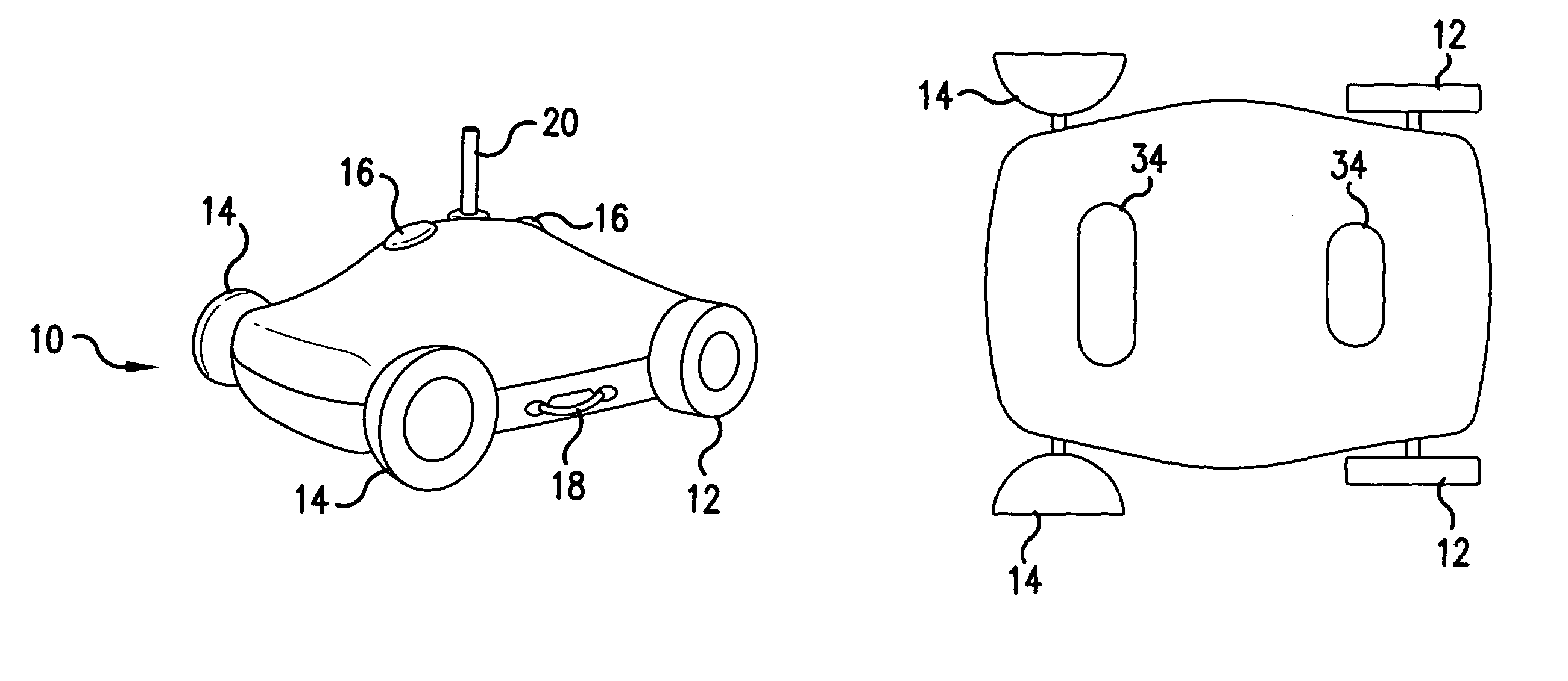
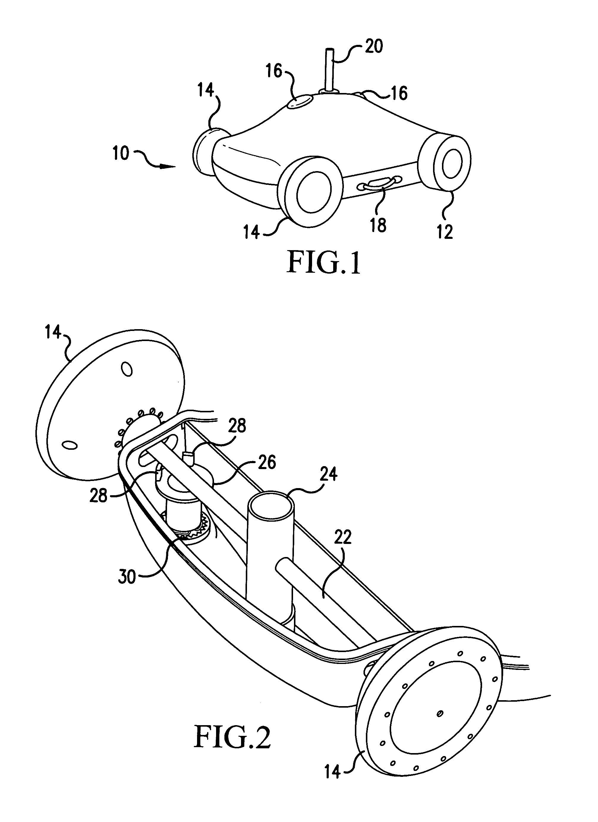
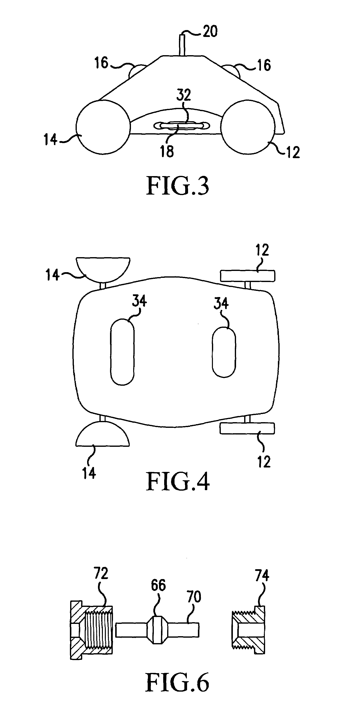
[0032]Referring now to the drawings, wherein like reference numerals designate identical corresponding parts throughout the several views, and more particularly, FIG. 1 thereof, wherein the pool cleaning device is seen as reference numeral 10. The device includes a body which is generally rectangular, having a domed top. The device includes a pair of front wheels 14 and a pair of rear wheels 12. Each pair of wheels is connected to an axle and fixedly connected thereto. Handles 18 are provided on the sides of the device for convenient lifting. Handles are made hollow, to provide buoyancy. Nozzles 16 are directed in opposite directions toward the front and back. These nozzles are utilized for propulsion as will be described later. A power cord 20 enters the device from the top in a watertight connection.

[0033]The power cord is connected to a motor and pump arrangement (not shown) which is arranged inside the device. As the motor turns the pump, water is first sucked up through the bot...


PUM


Abstract

A self-propelled swimming pool cleaner which randomly covers the bottom of the pool. Water pumped from the bottom of the unit filters dirt carried thereby, then uses the pumped water to propel the device either forward or backward. A pivoted front axle causes the path of the unit to vary when changing from forward to backward so that the unit randomly covers the entire pool bottom. Spring loaded doors may be provided to allow water to exit when the unit is lifted out of the pool. A sealed motor unit has a metal portion to transfer heat from the motor.

Description

[0001]The present application claims priority under 35 U.S.C. § 119 on provisional application 60 / 349,231, filed Jan. 18, 2002, the entirety of which is hereby incorporated by reference.FIELD OF THE INVENTION[0002]The present invention is directed generally to a cleaning device for a swimming pool and more particularly, to a device for cleaning the bottom of a swimming pool and which changes direction upon hitting a wall.DESCRIPTION OF THE BACKGROUND ART[0003]Swimming pools are a convenient source of recreation and exercise for many people. For those fortunate enough to have a private pool at their own residence, the convenience is even greater. However, this facility also requires a great deal of cleaning to keep it free from dirt and bacterial growth. The desirability of the pool decreases greatly if it is dirty or has algae growing. Unfortunately, due to the large size of such a pool and its openness, it is subject to receiving a great deal of dirt and other foreign material whic...

Claims


Application Information

Patent Timeline
IPC IPC(8): E04H4/16
CPCE04H4/1654
Inventor HUI, JOSEPH WING-TAK
Owner SMARTPOOL
Learn More