Method for optimizing the operating mode and combustion processes of a diesel engine

a technology of operating mode and combustion process, which is applied in the direction of combustion engines, electric control, machines/engines, etc., can solve the problems of not reproducible, soot values in particular become worse, and no suggestions on how to achieve them, so as to achieve the effect of reducing pollutant emissions

Active Publication Date: 2007-05-08
MAN ENERGY SOLUTIONS SA
View PDF18 Cites 19 Cited by
  • Summary
  • Abstract
  • Description
  • Claims
  • Application Information

AI Technical Summary

Benefits of technology

[0011]An object of the present invention is to elaborate the process of optimizing the operating and combustion processes of a diesel engine to minimize pollutant emissions in conjunction with the use of common rail injection and an exhaust gas turbocharger in such a way that the enthalpy of the exhaust gas can be temporarily increased internally in the engine by configuring the course of the injection process, with the result that the power output at the exhaust gas turbine is increased and, as a result of the mechanical coupling between the turbine and the compressor, the air mass flow and the charging air pressure on the compressor side can also be increased.

Problems solved by technology

The previously known methods offer no suggestions on how to accomplish this.
If the interval is too short, however, the results are not reproducible.
Conversely, if the interval is too long, the soot values in particular become worse, since the post-injected amount itself forms soot.

Method used


Image

  • Method for optimizing the operating mode and combustion processes of a diesel engine
  • Method for optimizing the operating mode and combustion processes of a diesel engine
  • Method for optimizing the operating mode and combustion processes of a diesel engine

Examples


Embodiment Construction

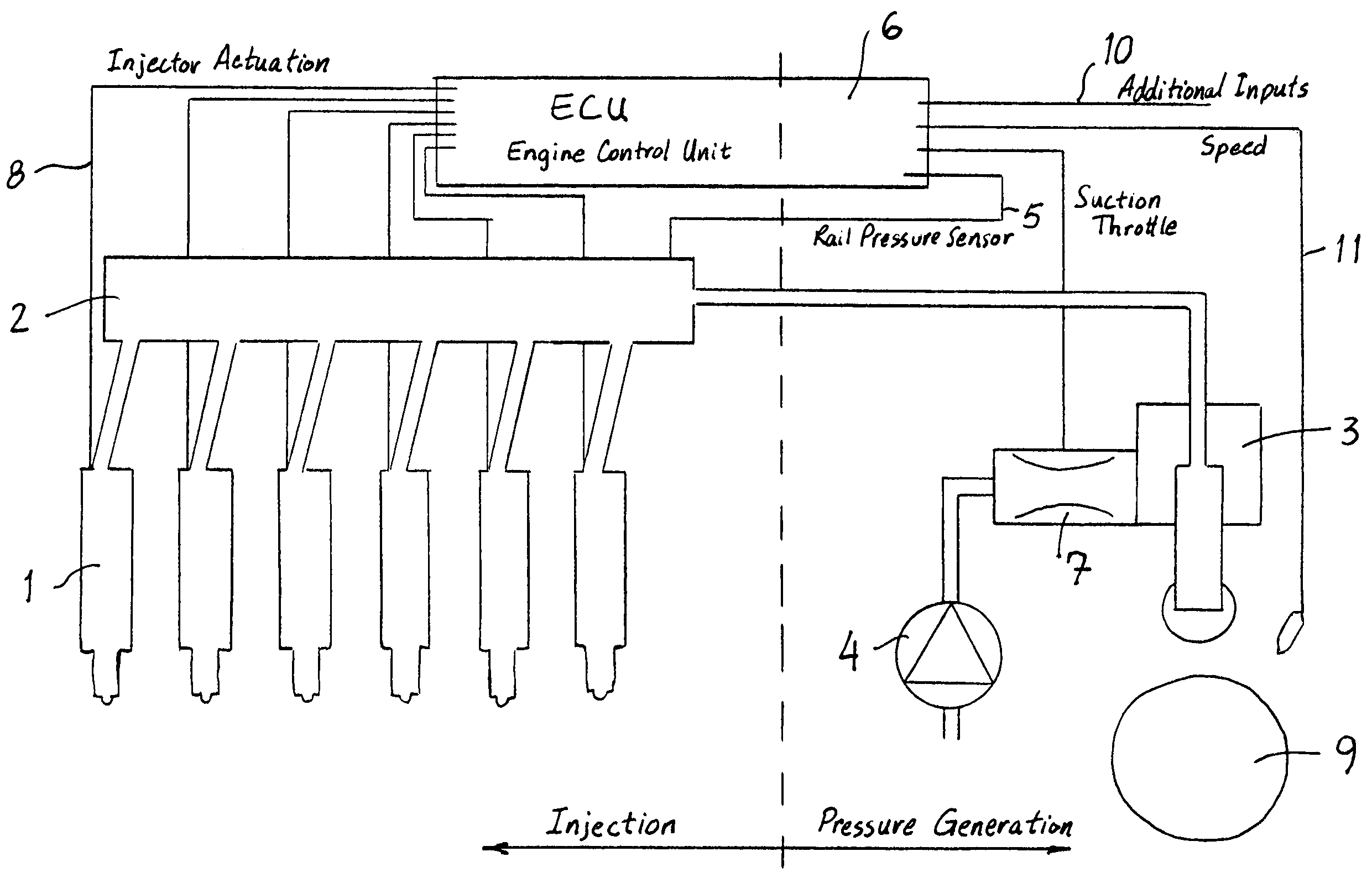
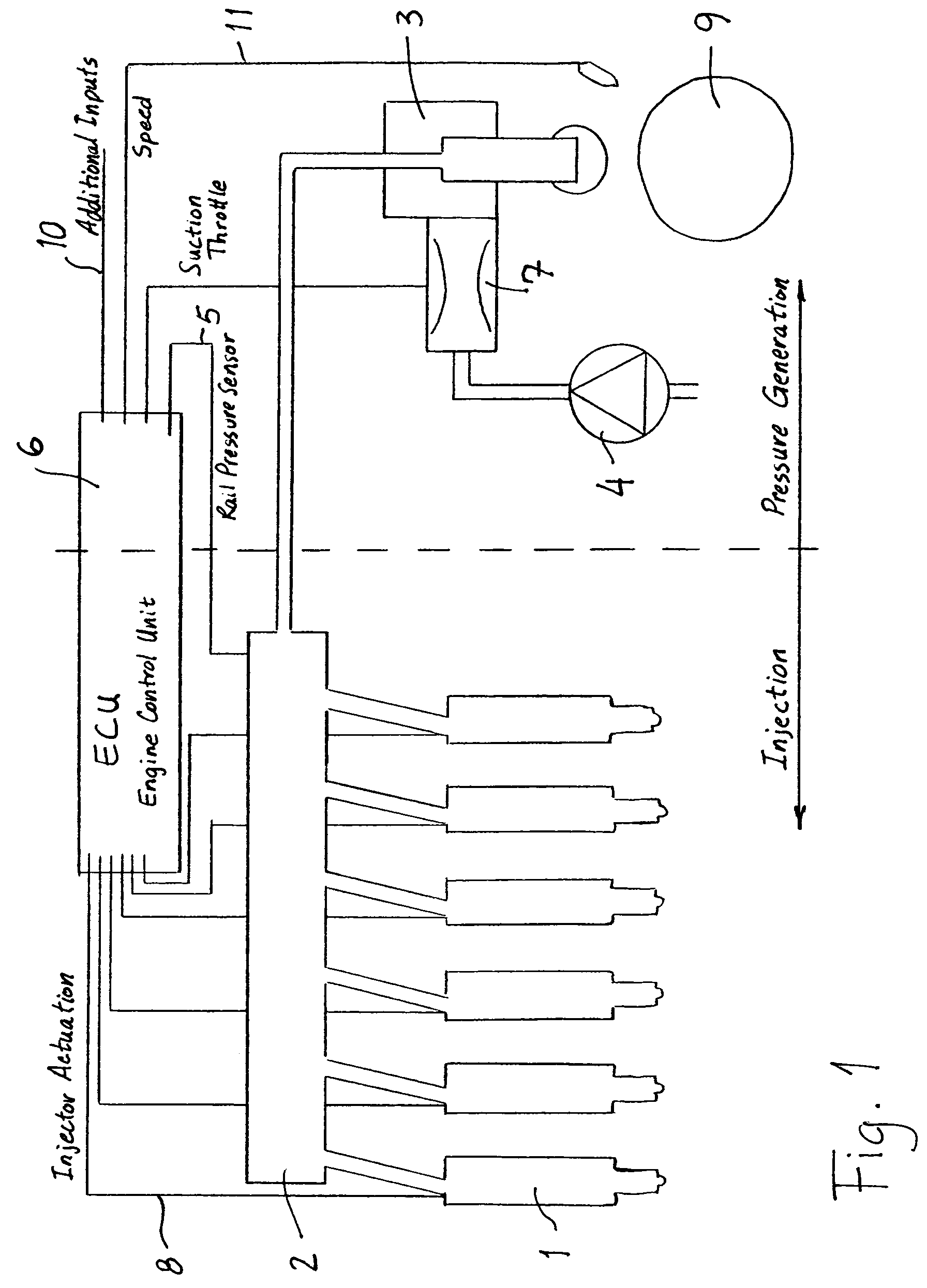
[0019]In a multicylinder diesel engine with turbocharging, fuel metering is controlled by an electronic valve or by a solenoid valve. The common rail injection system illustrated in FIG. 1 shows that an injector 1 is assigned to each cylinder (here a six-cylinder engine) of the internal combustion engine. The injectors 1 meter fuel to the internal combustion engine as a function of the actuation 8 of the solenoid valves. The injectors 1 are hydraulically connected in the known manner to a high-pressure fuel accumulator (rail) 2, which is supplied with fuel from a fuel storage tank 4 by a high-pressure pump 3 (controlled here by a camshaft 9). If at all possible, the high-pressure pump 3 supplies the high-pressure fuel accumulator 2 only with the amount of fuel that will then be removed by the injectors 1.

[0020]To this end, the amount of fuel delivered by the high-pressure pump 3 can be controlled as a function of the pressure in the high-pressure fuel accumulator 2. To detect the pr...


PUM


Abstract

A method for optimizing the operating and combustion processes of a diesel engine with common rail injection and a turbocharger includes injecting fuel into each combustion chamber of the diesel engine by a main injection and a post-injection which follows the main injection and controlling a start time and a quantity of the post-injection as a function of an end of the main injection and as a function of operating parameters of the diesel engine using an electronic engine control unit and an input-output map stored in the electronic engine control unit. The post-injection is initiated at a point 30–180° of rotation of a crankshaft of the diesel engine after the end of the main injection, and the quantity of the post-injection is adjusted to 20–30% of a quantity of the main injection.

Description

PRIORITY CLAIM[0001]This is a U.S. national stage of application No. PCT / EP2004 / 001722, filed on 21 Feb. 2004. Priority is claimed on the following application: Country: Germany, Application No.: 103 08 789.3, Filed: 28 Feb. 2003.BACKGROUND OF THE INVENTION[0002]The invention pertains to a method for optimizing the operating and combustion processes of a diesel engine with common rail injection with the goal of minimizing pollutant emissions in which fuel is injected into each combustion chamber of the diesel engine by at least a main injection and a post-injection following the main injection.[0003]Against the background of increasingly stringent emission standards (TA Luft=Technical Committee on Air), especially for stationary installations, power plants, pumping stations, and compressor installations, the lowering of pollutant values for nitrogen oxides is receiving more and more emphasis in engine development.[0004]For example, DE 198 36 053 A1 describes a system for the automat...

Claims


Application Information

Patent Timeline
Patent Type & Authority Patents(United States)
IPC IPC(8): F02B3/00F02B5/00F02B3/06F02D23/02F02D41/00F02D41/38F02D41/40
CPCF02D23/02F02D41/3827F02D41/405F02B3/06F02B2275/14F02D41/0007Y02T10/44Y02T10/123Y02T10/144Y02T10/12Y02T10/40F02D41/38F02D41/40
Inventor GRUNAUG, PETERHAAS, STEPHANHEIDER, GUNTER
Owner MAN ENERGY SOLUTIONS SA
Why Eureka
Try Eureka