
Heat shield arrangement for a component guiding a hot gas in particular for a combustion chamber in a gas turbine

a technology of hot gas and heat shield, which is applied in the direction of mechanical equipment, machines/engines, light and heating apparatus, etc., can solve the problems of excessive cooling air consumption, more cooling air used, and overall efficiency of the unit, so as to prevent residual coolant leakage, reduce coolant consumption further, and simple but effective measures

Inactive Publication Date: 2010-12-14
SIEMENS ENERGY GLOBAL GMBH & CO KG
View PDF26 Cites 24 Cited by
  • Summary
  • Abstract
  • Description
  • Claims
  • Application Information

AI Technical Summary

Benefits of technology

This solution reduces coolant consumption and pollutant emissions by ensuring a precise and controlled coolant application, enhancing cooling efficiency and sealing effectiveness while minimizing the mass flow of cooling air, thereby improving the overall efficiency and reducing NOx emissions.

Problems solved by technology

The uncontrolled blowing out of the cooling air however means that more cooling air is used to seal the gaps than is required for the cooling task.
This increase in quantity leads to excessive cooling air consumption with disadvantageous consequences for the overall efficiency of the unit and pollutant emissions from the combustion system producing the hot gas.

Method used


Image

  • Heat shield arrangement for a component guiding a hot gas in particular for a combustion chamber in a gas turbine
  • Heat shield arrangement for a component guiding a hot gas in particular for a combustion chamber in a gas turbine
  • Heat shield arrangement for a component guiding a hot gas in particular for a combustion chamber in a gas turbine

Examples


Embodiment Construction

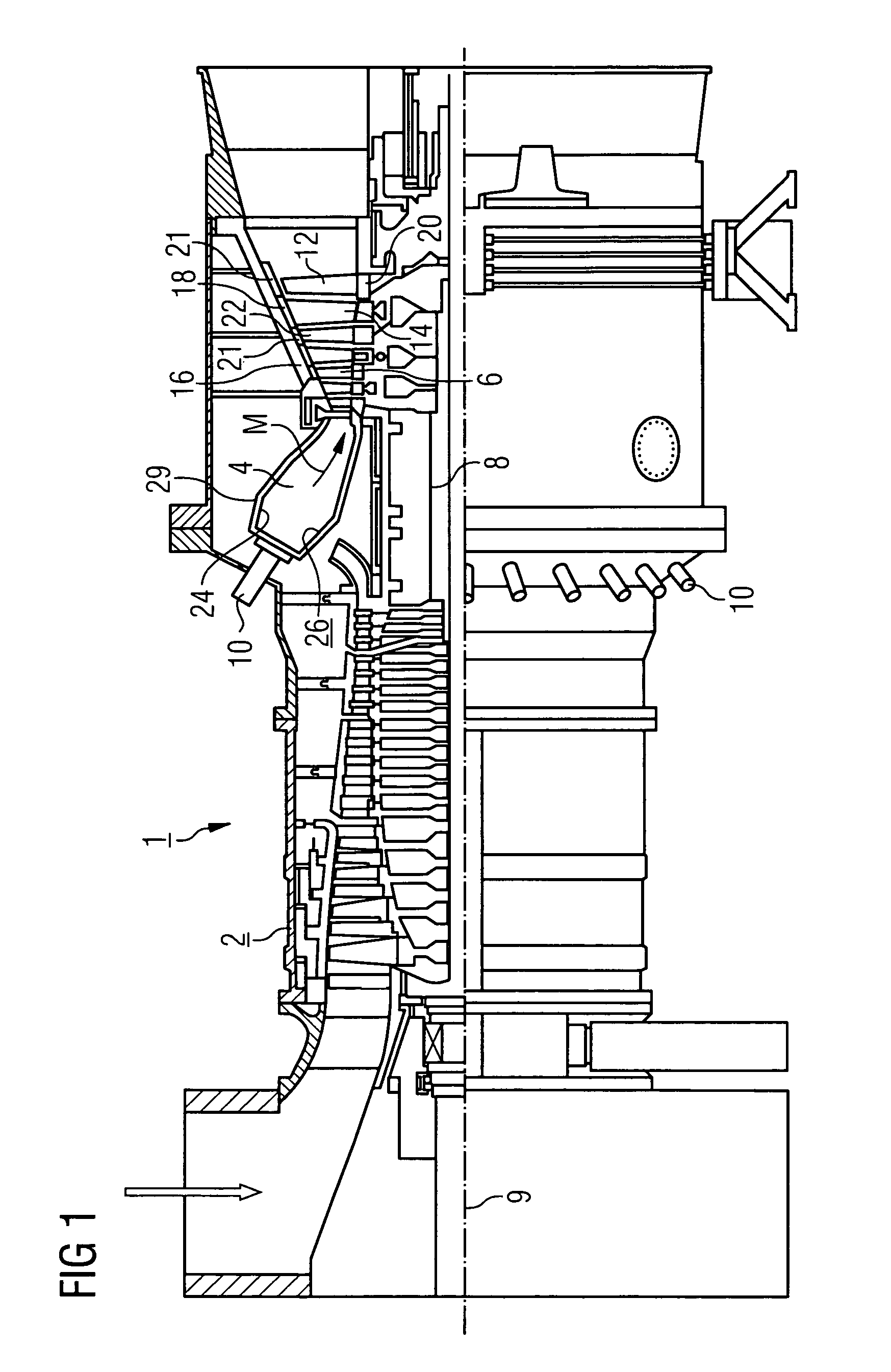
[0028]The gas turbine 1 according to FIG. 1 has a compressor 2 for the combustion air, a combustion chamber 4 and a turbine 6 to drive a compressor 2 and a generator or machine (not shown in further detail here). To this end the turbine 6 and compressor 2 are disposed on a common turbine shaft 8 also referred to as a turbine rotor, to which the generator or machine is also connected, and which is supported such that it can be rotated about its central axis 9. The combustion chamber 4 configured in the manner of an annular combustion chamber is fitted with a number of burners 10 to burn a fluid or gaseous fuel.

[0029]The turbine 6 has a number of rotating blades 12 connected to the turbine shaft 8. The blades 12 are disposed in a rim shape on the turbine shaft 8, thereby forming a number of rows of blades. The turbine 6 also has a number of fixed vanes 14, which are also fixed in a rim shape, forming rows of vanes on an internal housing 16 of the turbine 6. The blades 12 thereby serve...


PUM


Abstract

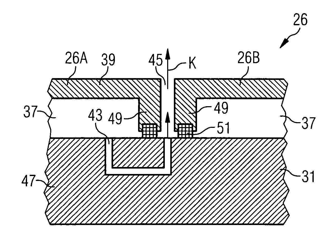
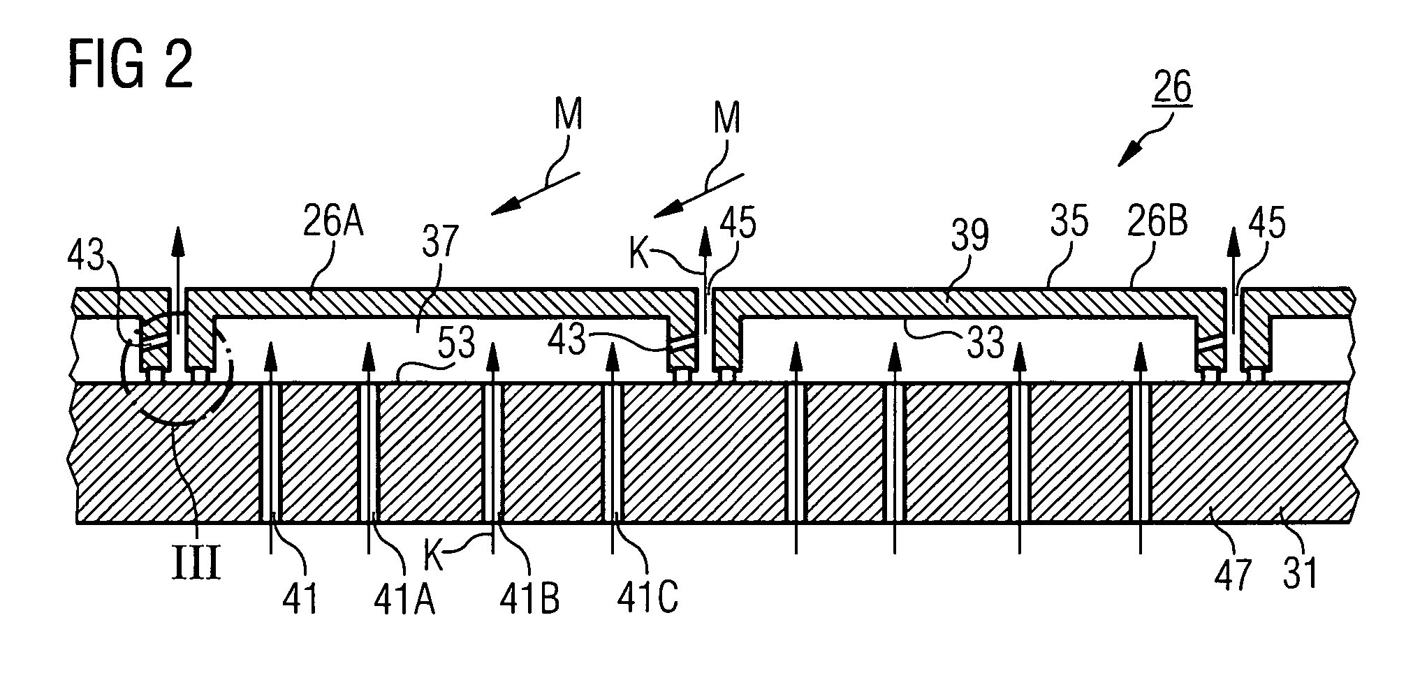
The invention relates to a heat shield arrangement for a hot gas (m)-guiding component, which comprises a number of heat shield elements arranged side-by-side on a supporting structure while leaving a gap there between. A heat shield element can be mounted on the supporting structure whereby forming an interior space which is delimited in areas by a hot gas wall to be cooled, with an inlet channel for admitting a coolant into the interior space. According to the invention, a coolant discharge channel is provided for the controlled discharge of coolant from the interior space and, from the interior space, leads into the gap. Coolant can be saved and efficiently used by the specific coolant discharge via the coolant discharge channel, and reduction in pollutant emissions can also be achieved. The heat shield arrangement is particularly suited for linking a combustion chamber of a gas turbine.

Description

CROSS REFERENCE TO RELATED APPLICATIONS[0001]This application is the US National Stage of International Application No. PCT / EP2004 / 008116, filed Jul. 20, 2004 and claims the benefit thereof. The International Application claims the benefits of European Patent application No. EP03018415.4 filed Aug. 13, 2003. All of the applications are incorporated by reference herein in their entirety.FIELD OF THE INVENTION[0002]The invention relates to a heat shield arrangement for a component guiding a hot gas, which comprises a number of heat shield elements disposed next to each other on a supporting structure with gaps in between. A heat shield element can be mounted on the supporting structure such that an internal space is formed, which is delimited in areas by a hot gas wall to be cooled, with an inlet channel for admitting a coolant into the internal space. The invention also relates to a combustion chamber with an internal combustion chamber lining, which has such a heat shield arrangemen...

Claims


Application Information

Patent Timeline
Patent Type & Authority Patents(United States)
IPC IPC(8): F02C1/00F23M5/02F23M5/08F23R3/00
CPCF23M5/02F23M5/085F23R3/002F23R2900/00012
Inventor DAHLKE, STEFANPUTZ, HEINRICH
Owner SIEMENS ENERGY GLOBAL GMBH & CO KG
Learn More