Burner

a burner and fuel technology, applied in the field of burners, can solve the problems of shortening the ignition delay time, reducing the ignition temperature, and unsuitable conventional burners for use with hydrogen gas-containing fuels, and achieving the effect of reducing pollutant emissions and improving intermixing of fuels

Inactive Publication Date: 2009-11-12
ANSALDO ENERGIA IP UK LTD
View PDF14 Cites 21 Cited by
  • Summary
  • Abstract
  • Description
  • Claims
  • Application Information

AI Technical Summary

Benefits of technology

[0006]This is where the present invention comes in. The invention, as characterized in the claims, is concerned with the problem of specifying for a burner of the type initially mentioned an improved embodiment which is distinguished particularly in that the burner allows an improved intermixing of fuel and oxidizer and therefore reduced pollutant emissions, even when it is operated with a fuel containing hydrogen gas.
[0008]The invention is based on the general idea of using, instead of a cylindrical lance arranged coaxially in the burner, a rectilinear streamlined body which is arranged in the burner such that it extends with its longitudinal direction perpendicularly or at an inclination to a main flow direction prevailing in the burner, the at least one nozzle of this body possessing its outlet orifice at a trailing edge of the streamlined body. Streamlined bodies are distinguished by low flow resistance, which here is conducive to the throughflow of the burner. They also avoid wakes and recirculation zones in which fuel could ignite. By the at least one nozzle being arranged at the trailing edge or slightly upstream of the trailing edge, the fuel gas can be introduced into the burner, for example, in the flow direction of the oxidizer gas, thus reducing the risk of a concentration of the fuel gas in a wall region of the burner. Injection with a small angle relative to the main flow direction is possible, as long as recirculation of fuel gas due to eddies, which can form in the wake of fuel jet penetrating into the main flow, is avoided.
[0009]The streamlined body expediently extends over the entire height of a flow cross section of the burner. By virtue of this type of construction, the streamlined body extends from one portion of the burner wall as far as an opposite wall portion, without additional holding devices being required. As a result, a homogeneous flow profile over the entire height of the flow cross section and therefore constant introduction conditions over the entire length of the streamlined body can be implemented. Overall, the introduction of fuel can also thereby be equalized.
[0010]According to a particularly advantageous embodiment, the burner may additionally be provided with introduction devices for introducing additional media, for example a further fuel or a carrier gas, the introduction devices introducing the additional media into the burner via at least one outlet orifice which is likewise arranged at the trailing edge of the streamlined body. In the case of a carrier gas, which may likewise be an oxidizer gas, in particular air, the intermixing of fuel gas with oxidizer gas can be improved. To this end it can be injected at a small angle relative to the main flow. Further, the carrier gas is typically cooler than the main airflow. It can therefore increase the ignition delay time of the fuel gas in the oxidizer flow and thereby increase the time available for mixing. Further, it can serve to cool the streamlined body.

Problems solved by technology

Conventional burners are unsuitable for use with such a fuel containing hydrogen gas.
In comparison with natural gas, a fuel gas containing hydrogen gas possesses markedly higher reactivity, which leads to lower ignition temperatures, shorter ignition delay times and higher flame velocities.
Moreover, the risk of flashbacks rises.
In conventional burners, however, this may lead to the fuel gas possessing an increased concentration in the region of a burner wall, which ultimately may likewise lead to increased pollutant values and even flashback, at the latest in the combustion chamber.

Method used


Image

  • Burner
  • Burner
  • Burner

Examples


Embodiment Construction

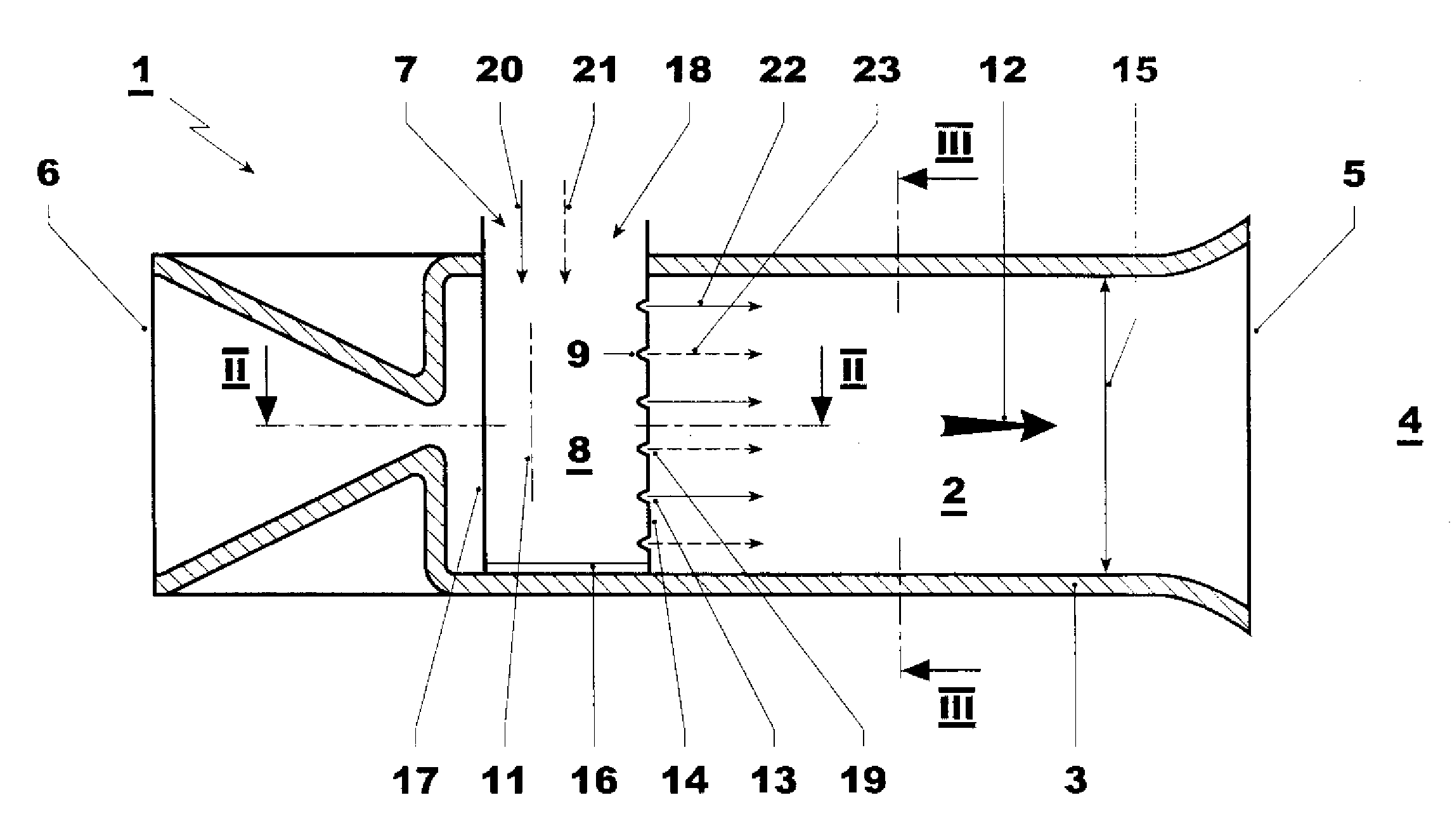
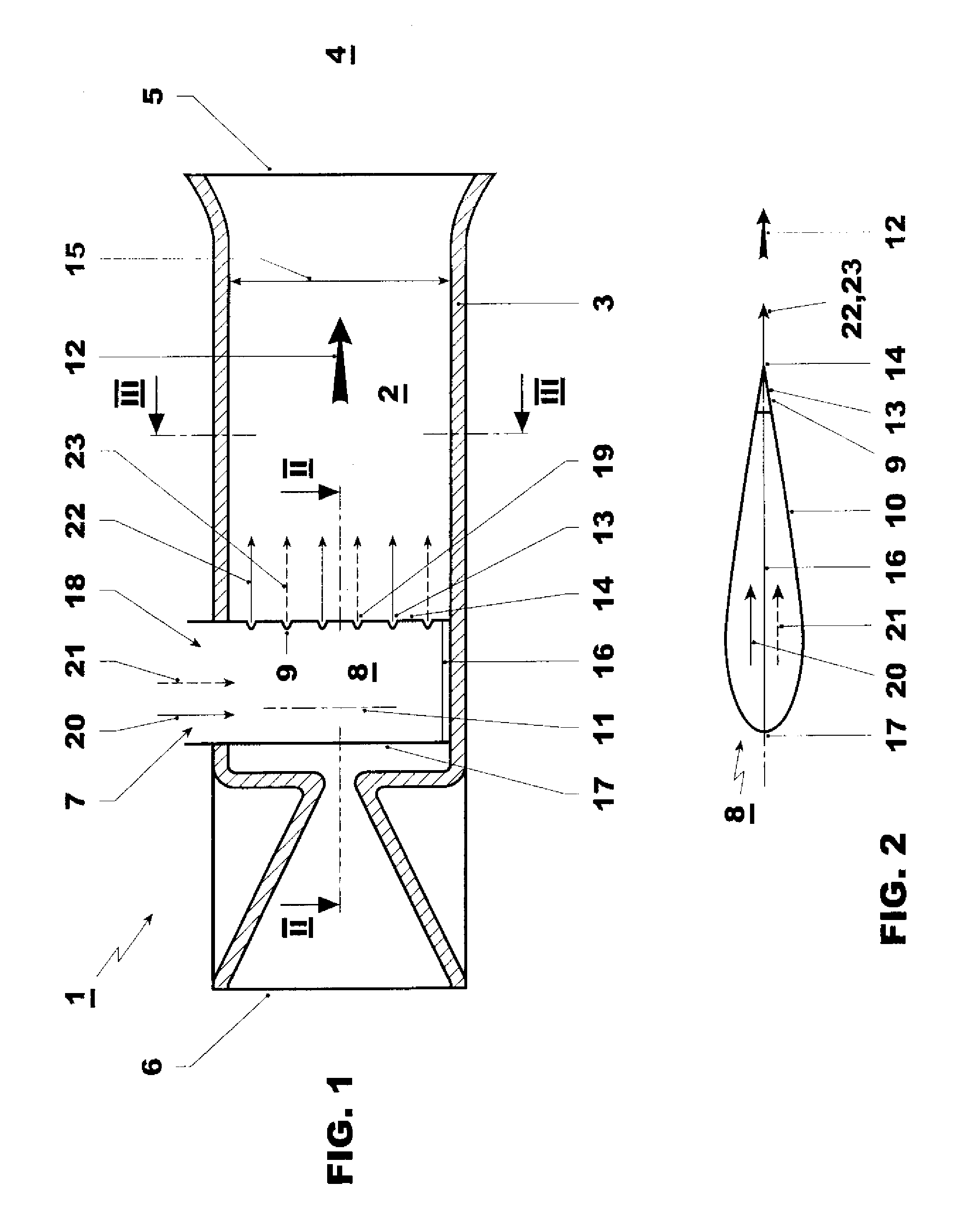
[0016]According to FIG. 1, a burner 1 comprises a mixing space 2 which is delimited by a burner wall 3. The burner 1 expediently forms an integral part of a combustion chamber, of which only a combustion space 4 is indicated here. Said combustion space 4 adjoins an outlet side 5 of the burner 1, through which a gas flow can emerge from the mixing space 2 and into the combustion space 4. Furthermore, the burner 1 has an inlet side 6, through which, when the burner 1 is in operation, an oxidizer flow, preferably an air flow, enters the mixing space 2 of the burner 1.

[0017]The burner 1, moreover, has an injection device 7, with the aid of which a gaseous fuel is introduced into the burner 1 or into its mixing space 2. The fuel is, in particular, a fuel which contains hydrogen gas and, in particular, carbon monoxide gas and which can be produced synthetically, for example by coal gasification.

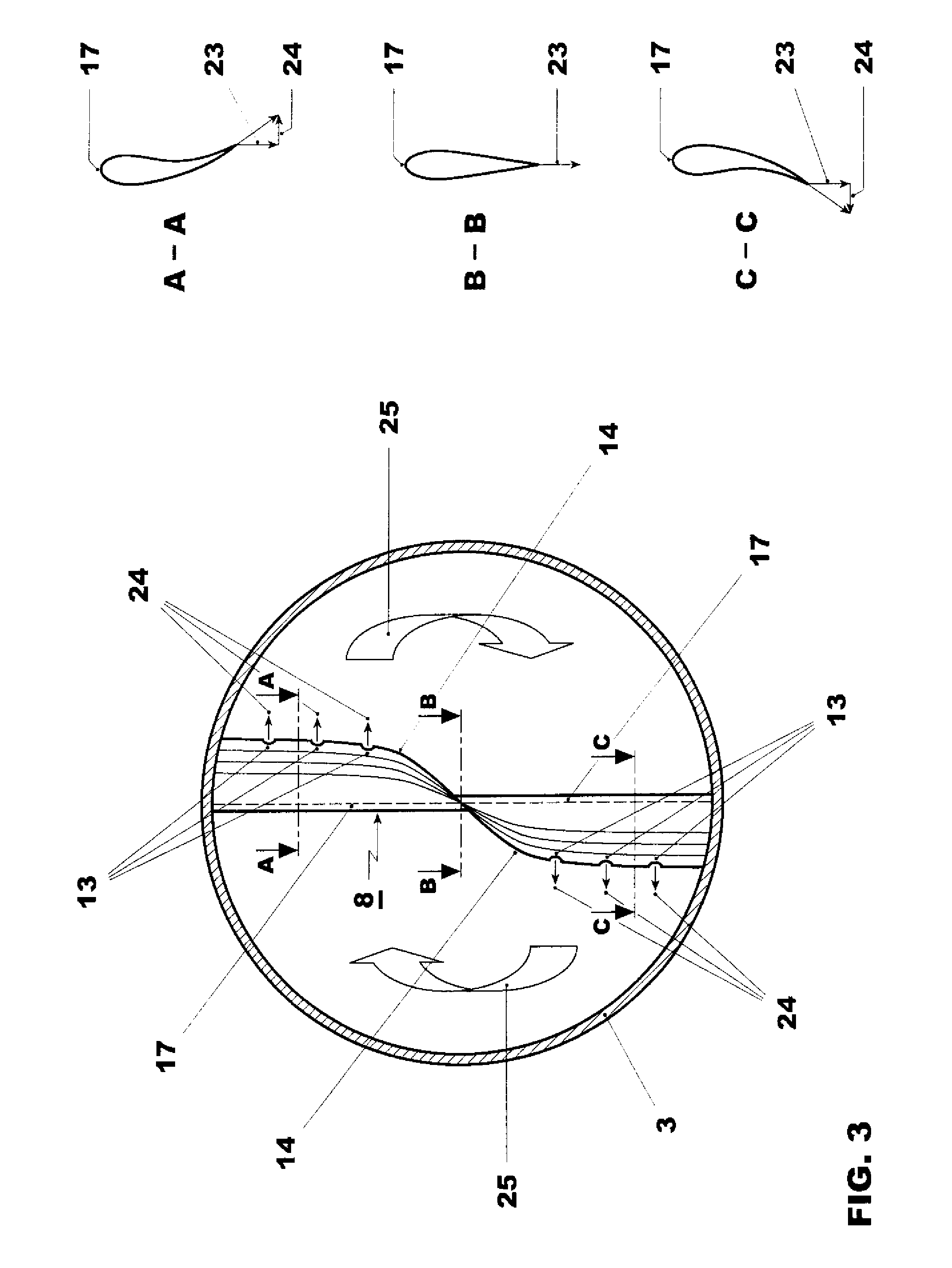
[0018]The injection device 7 has a body 8 which is arranged in the burner 1, that is to say in ...


PUM


Abstract

The present invention relates to a burner for a combustion chamber of a gas turbine plant, with an injection device for introducing gaseous fuel into the burner. The injection device has a body which is arranged in the burner and which has at least one nozzle for introducing gaseous fuel into the burner. The body is configured as a streamlined body which has a streamlined cross-sectional profile and which extends with a longitudinal direction transversely with respect to a main flow direction prevailing in the burner. The at least one nozzle has its outlet orifice at an trailing edge of the streamlined body.

Description

FIELD OF THE INVENTION[0001]The present invention relates to a burner for a second combustion chamber of a gas turbine plant with sequential combustion having a first and a second combustion chamber.BACKGROUND OF THE INVENTION[0002]Combustion chambers of gas turbine plants are conventionally equipped with one burner or with a plurality of burners. A burner of this type may be equipped, for example for pilot operation or for stabilizing a flame front in the combustion chamber, with an injection device for introducing gaseous and / or liquid fuel into the burner. An injection device of this type comprises a body which is arranged in the burner and which has at least one nozzle for introducing the fuel into the burner. The injection device is conventionally a lance as known for example from the DE4326802, the shaft of which forms the body arranged in the burner and usually equipped with a plurality of nozzles. In this case, a configuration is customary in which the nozzles introduce the ...

Claims


Application Information

Patent Timeline
Patent Type & Authority Applications(United States)
IPC IPC(8): F02C7/22
CPCF23C2900/07001F23D14/64F23R3/286F23D2900/14021F23D2900/14004
Inventor CARRONI, RICHARDPOYYAPAKKAM, MADHAVAN NARASIMHANBIALKOWSKI, MICHALWILLETTS, MARK ANDREW
Owner ANSALDO ENERGIA IP UK LTD
Why Eureka
Try Eureka