Heat exchanger assembly having fitting secured thereto and method of securing the same

a technology of heat exchanger and fitting, which is applied in the direction of electrical equipment, electrical equipment contruction details, lighting and heating equipment, etc., can solve the problems of fitting dislocation or loosening, tool damage, and fitting rotation movement, so as to prevent rotational movement of fittings, overcome inadequacies, and increase the resistance to other stresses

Active Publication Date: 2007-05-08
MAHLE INT GMBH
View PDF19 Cites 5 Cited by
  • Summary
  • Abstract
  • Description
  • Claims
  • Application Information

AI Technical Summary

Benefits of technology

[0006]The method of securing the fitting includes the steps of disposing the first end of the fitting into the aperture and inserting a tool within the fitting from a direction outside of the tank. Inserting the tool results in radially and longitudinally displacing at least a part of the step of material relative to the axis into contact with the wall. The displaced part of the step secures the fitting into the aperture and prevents rotational movement of the fitting.
[0007]The subject invention overcomes the inadequacies that characterize the related art assemblies. Specifically, the radial and longitudinal displacement of the step of material prevents rotational movement of the fitting when connectors are attached thereto. Further, the subject invention has increased resistance to other stresses as a result of the step of material being radially and longitudinally displaced. Certain uses of the fitting, such as a threaded fitting, must have strength to withstand sufficient shear forces. The subject invention provides sufficient rotational strength to accommodate such shear forces. Additionally, the method, according to the subject invention, allows the fittings to be secured to tank from outside of the tank. Therefore, the fitting can be secured to the tank after the tank has been manufactured which reduces the likelihood that the fitting may become dislodged or loosed during the manufacturing of the tank.

Problems solved by technology

One disadvantage of such a method is that the fitting must be attached to the tank from inside the tank.
The fitting may become dislodged or loosened as the manufacturing of the tank is completed or the fitting may prevent the tank from being assembled.
The swaging of the tubes limits movement of the tubes and does not prevent rotational movement of the tubes.
One disadvantage of these swaging methods is that the tools are generally expandable and flexible resulting in the tools being very fragile.
Specifically, the fitting is secured to the tank from inside the tank and the fitting may become loosened during the manufacturing of the tank and prevent the tank from being assembled.
Further, smaller tanks or apertures of the tank that are obscured may not have access to secure the fitting from the inside.
Additionally, the related art does not provide methods or assemblies to prevent rotational movement or add rotational strength of the fitting once connected to the tank.
This rotational force results in the fittings of the related art becoming disconnected from the tank or loosened such that fluid may leak therefrom.

Method used


Image

  • Heat exchanger assembly having fitting secured thereto and method of securing the same
  • Heat exchanger assembly having fitting secured thereto and method of securing the same
  • Heat exchanger assembly having fitting secured thereto and method of securing the same

Examples


Embodiment Construction

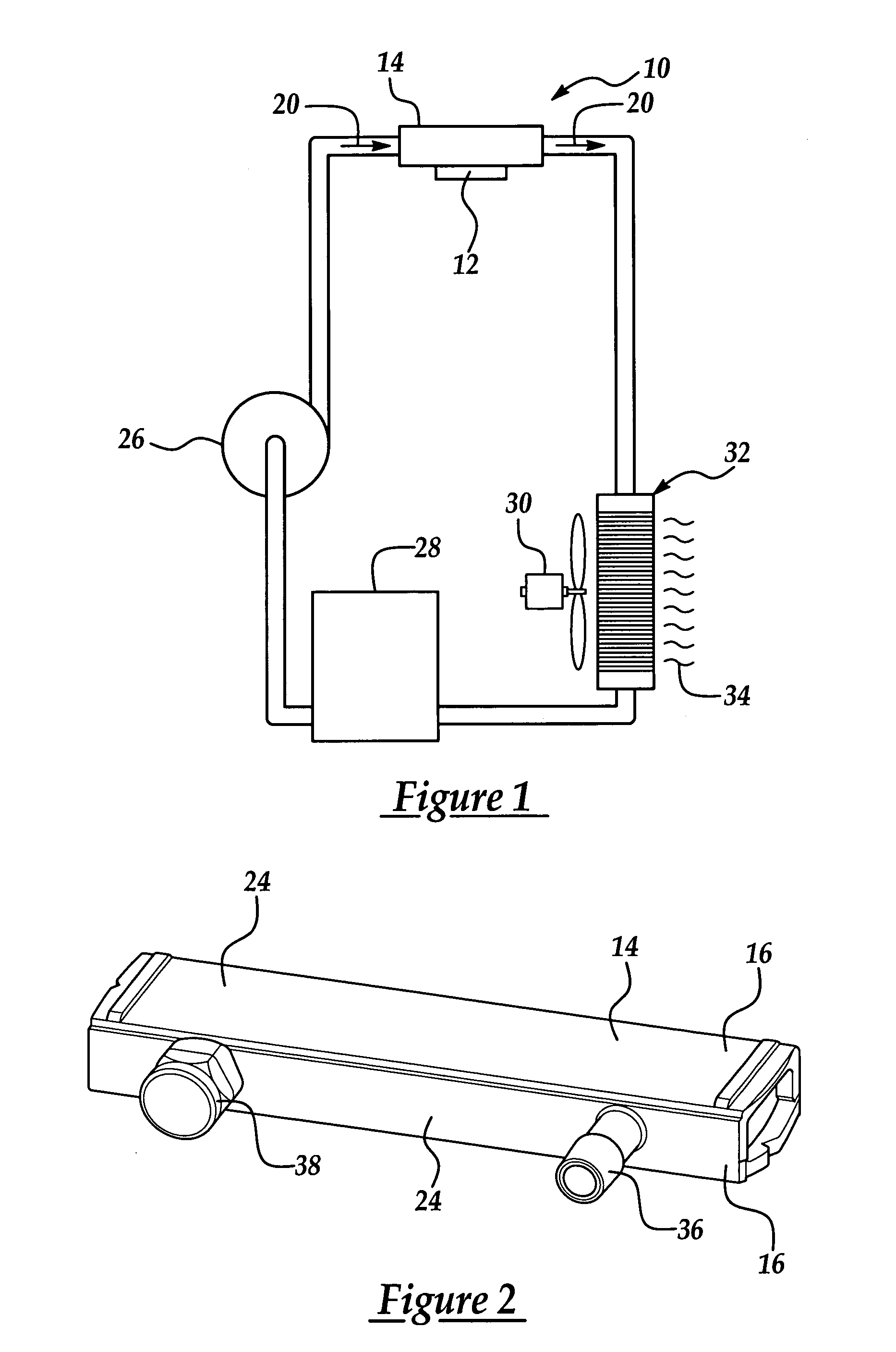
[0018]Referring to the Figures, wherein like numerals indicate corresponding parts throughout the several views, a heat exchanger assembly is shown generally at 10 in FIG. 1. The heat exchanger assembly 10 is preferably a liquid cooling unit (LCU) for cooling a device 12. The subject invention finds additional uses in other industries, such as, automotive, medical, heating, ventilation, and air cooling, commercial, and the like. For example, the subject invention may be employed with any assembly that conveys fluid through an enclosed volume. The subject invention is particularly useful with electronic devices such as, but not limited to, computer chips, telecommunication chips, microprocessor assemblies, and the like. These electronic devices are used in various systems (not shown), such as computer systems, telecommunication systems, and the like.

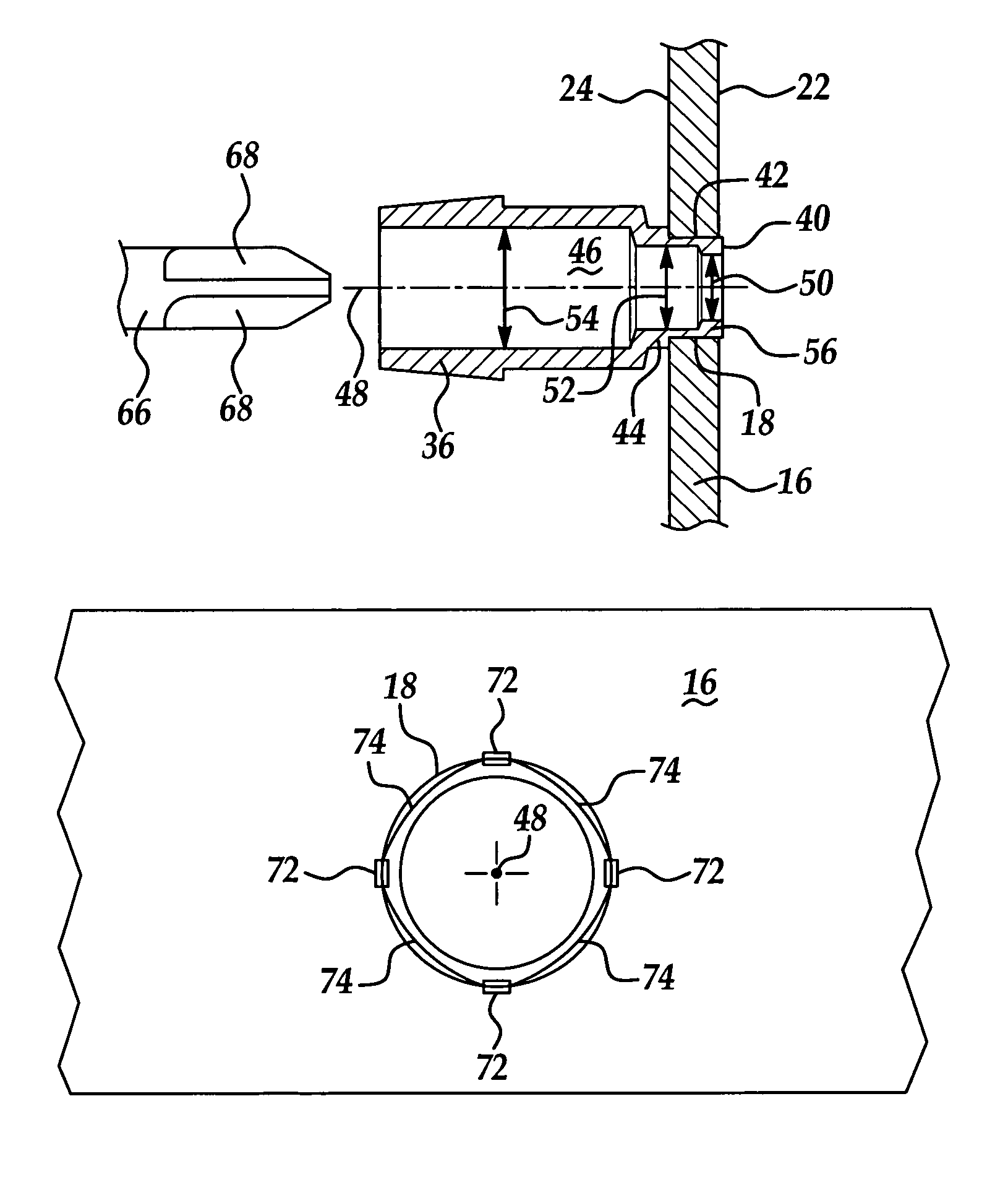
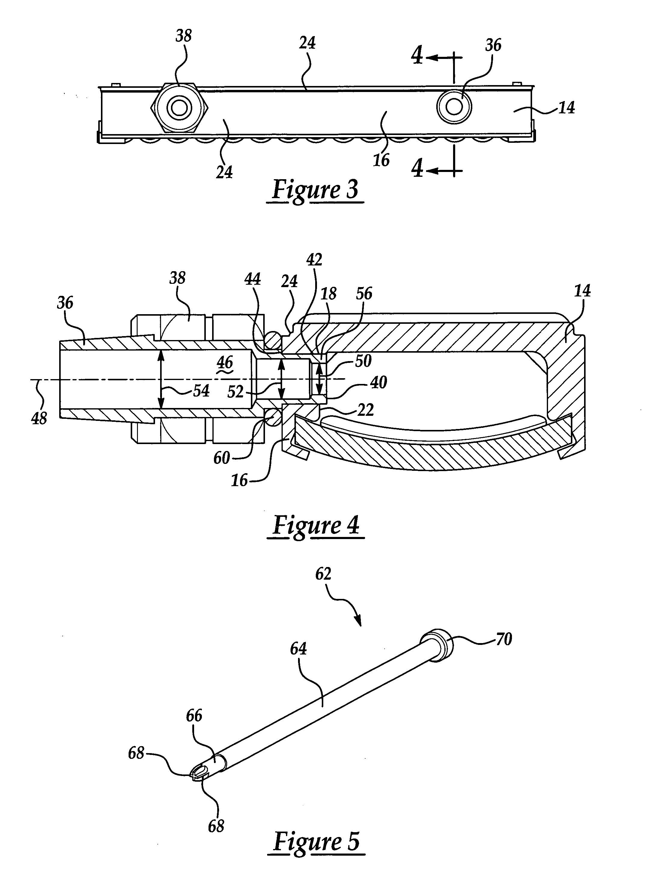
[0019]The heat exchanger assembly 10 includes a tank 14 having a wall 16 defining an aperture 18. As appreciated by those skilled in the...


PUM


Abstract

The subject invention provides a heat exchanger assembly including a tank having a wall defining an aperture with a fitting secured thereto and a method of securing the fitting thereto. The fitting has a first end with an outer perimeter disposed exteriorly thereof and smaller than the aperture for inserting the first end of the fitting into the aperture. The fitting also has an internal tunnel extending along an axis thereto from the first end. A step of material is disposed in the tunnel at the first end, which is at least in part, radially and longitudinally displaced relative to the axis into contact with the wall to prevent rotational movement of the fitting in the aperture.

Description

TECHNICAL FIELD[0001]The subject invention relates to a heat exchanger assembly, and more specifically, a liquid cooling unit having a fitting secured thereto and a method of securing the same.BACKGROUND OF THE INVENTION[0002]Various methods are known for attaching fittings to components of heat exchanger assemblies. Generally, the component includes a wall defining an aperture and the fitting is positioned in the aperture. Next, from inside of the tank, a tool is used to expand a portion of the fitting to have an interference fit with the wall. One disadvantage of such a method is that the fitting must be attached to the tank from inside the tank. The tank is typically enclosed such that the fitting must be secured to the tank prior to the tank being sealed. In other words, the fitting is connected before the manufacturing of the tank is complete. The fitting may become dislodged or loosened as the manufacturing of the tank is completed or the fitting may prevent the tank from bein...

Claims


Application Information

Patent Timeline
Patent Type & Authority Patents(United States)
IPC IPC(8): F28D7/00
CPCF28D15/00F28F9/0246H05K7/20272
Inventor FULLER, CHRISTOPHER ALFRED
Owner MAHLE INT GMBH
Why Eureka
Try Eureka