Image coding device and method of image coding

a coding device and image technology, applied in the field of image coding devices, can solve the problems of affecting the frame rate output at the decoding side, the resultant quality of the coded image is drastically deteriorated, and the inability to arrange, so as to achieve the effect of reducing the amount of coding and raising the efficiency of coding

Inactive Publication Date: 2007-05-08
MITSUBISHI ELECTRIC CORP
View PDF18 Cites 15 Cited by
  • Summary
  • Abstract
  • Description
  • Claims
  • Application Information

AI Technical Summary

Benefits of technology

[0042]Due to this configuration, the efficiency of coding can be raised by raising the inter-relation of fields (specially the inner-relation in

Problems solved by technology

However, it is also well known that if the compression rate is to be made still higher, various noises in coding such as “block noise”, “mosquito noise” and so on, which are perceptible to the human's ears, are generated, so that the resultant quality of the coded images is drastically deteriorated.
However, since the conventional image coding method is configured as explained above, in the coding system like the MPEG 2 method in which the frame rate of a motion image signal is set to a constant level when output at its decoding time, it cannot be arranged such that

Method used


Image

  • Image coding device and method of image coding
  • Image coding device and method of image coding
  • Image coding device and method of image coding

Examples


first embodiment

[First Embodiment]

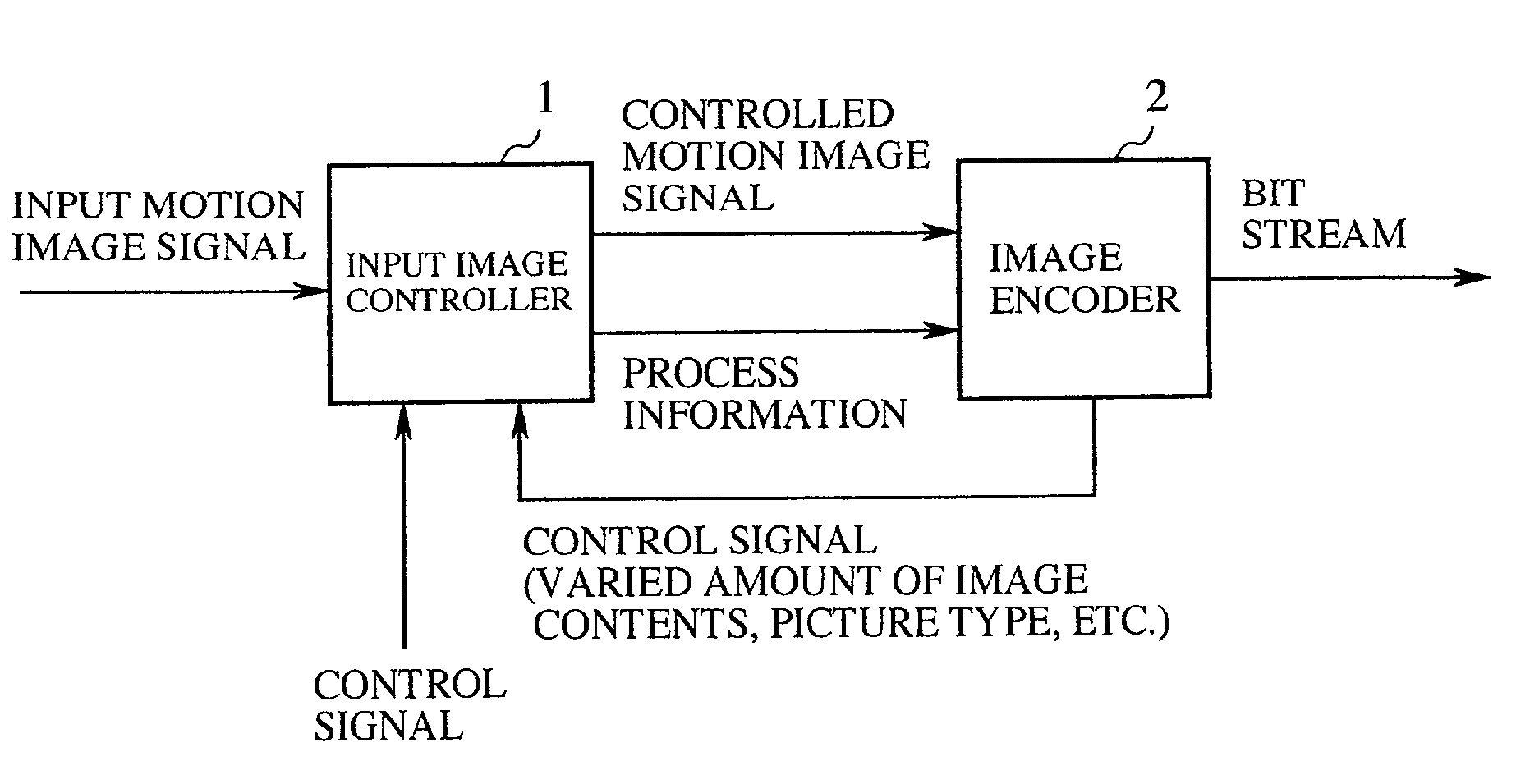
[0052]FIG. 1 is a schematic diagram showing the configuration of an image coding device according to a first embodiment of the present invention. In the figure, reference numeral 1 denotes an input image controller which, in the case where an input motion image signal is coded by a coding method such as the MPEG 2 (ISO / IEC 13818-2), which is standardized in the international level in conformity with the ISO / IEC, and prescribes such that the frame rate of a motion image signal should be made to a constant level before it is output, carries out a predetermined process with respect to the input motion image signal to reduce the amount of decoding, and also outputs the thus processed motion image signal, as well as the information showing the detail of the process for reducing the decoding amount (hereinafter may be referred to just as “process information”). Reference numeral 2 denotes an image coding device for coding the thus processed motion image signal (hereinaft...

second embodiment

[Second Embodiment]

[0068]The image coding device according to a second embodiment of the present invention is arranged such that the frame rate of the motion image signal after control is changed to another rate. It should be noted that the configuration of the image coding device according to the second embodiment is same as that of the first embodiment, so that the detailed explanation thereabout is omitted here.

[0069]Next, the operation of the image coding device of this embodiment is explained.

[0070]In the case where an input motion image signal is of the interlace mode, the input image controller 1 skips one field among each set of three fields, and the image coder 2 sets the overhead information such that one field out of each of the remaining sets of two fields is repetitively output twice at the decoding side, and codes the motion image signal after exclusion by the MPEG 2 method. FIG. 7 is an illustration showing one example of a motion image signal in the case where one fi...

third embodiment

[Third Embodiment]

[0076]The image coding device according to a third embodiment of the present invention is arranged such that a motion image signal after control is generated in such a manner that the first field and the second field of each frame of the input motion image signal are regarded as being the same fields, and that the frame rate of the motion image signal after control is not changed but same as that of the input motion image signal.

[0077]Note that the configuration of the image coding device according to the third embodiment is same as that of the first embodiment, so that the detailed explanation thereabout is omitted here. However, the input image controller 1 does not need to provide any process information to the image coder 2.

[0078]Next, the operation of the image coding device of this embodiment is explained.

[0079]FIG. 8 is an exemplary view showing one example of a motion image signal after control in the image coding device according to this third embodiment o...


PUM


Abstract

The input image controller reduces the frame rate of a motion image signal as a preprocessing, provides process information indicating the skipped frames and/or skipped fields to the image coder, wherein the image coder codes, by use of the MPEG 2 method, the motion image signal whose frame rate has been reduced, and outputs the data which is in conformity with the MPEG 2 method and includes overhead information on the basis of the process information.

Description

CROSS-REFERENCE TO THE RELATED APPLICATION [0001]This Application is a continuation of International Application No. PCT / JP00 / 04263, whose international filing date is Jun. 28, 2000, the disclosures of which Application are incorporated by reference herein.BACKGROUND OF THE INVENTION[0002]1. Field of the Invention[0003]The present invention relates to an image coding device, which is capable of coding motion image signals without affecting the frame rate thereof when output at the decoding side, and also relates to a method for coding motion image signals.[0004]2. Description of the Related Art[0005]When digitizing motion image signals, the resulting data amount often becomes enormous, and thus in the case for storing motion image signals in a recording medium such as an optical disk, or the case for broadcasting and / or communicating these motion image signals, a coding operation is applied to those motion image signals for the purpose of reducing the total data amount thereof.[0006...

Claims


Application Information

Patent Timeline
IPC IPC(8): H04N7/18G06T9/00H04N21/238H04N7/26H04N7/46H04N19/134
CPCG06T9/007H04N19/172H04N19/85H04N19/16H04N19/587H04N19/132H04N21/238H04N19/134
Inventor YAMADA, YOSHIHISATANNO, OKIKAZUASAI, KOHTAROMURAKAMI, TOKUMICHI
Owner MITSUBISHI ELECTRIC CORP
Why Eureka
Try Eureka