Digital focus lens system

a digital focus and lens technology, applied in the field of optical components, can solve problems such as optical loss and aberration of images

Inactive Publication Date: 2007-05-15
BATCHKO ROBERT G
View PDF38 Cites 129 Cited by
  • Summary
  • Abstract
  • Description
  • Claims
  • Application Information

AI Technical Summary

Problems solved by technology

Conventional variable-focus lens systems are bulky, require moving parts, or require numerous elements resulting in optical losses and aberration of the images.

Method used


Image

  • Digital focus lens system
  • Digital focus lens system
  • Digital focus lens system

Examples


Embodiment Construction

[0015]Although the following detailed description contains many specific details for the purposes of illustration, anyone of ordinary skill in the art will appreciate that many variations and alterations to the following details are within the scope of the invention. Accordingly, the embodiments of the invention described below are set forth without any loss of generality to, and without imposing limitations upon, the claimed invention.

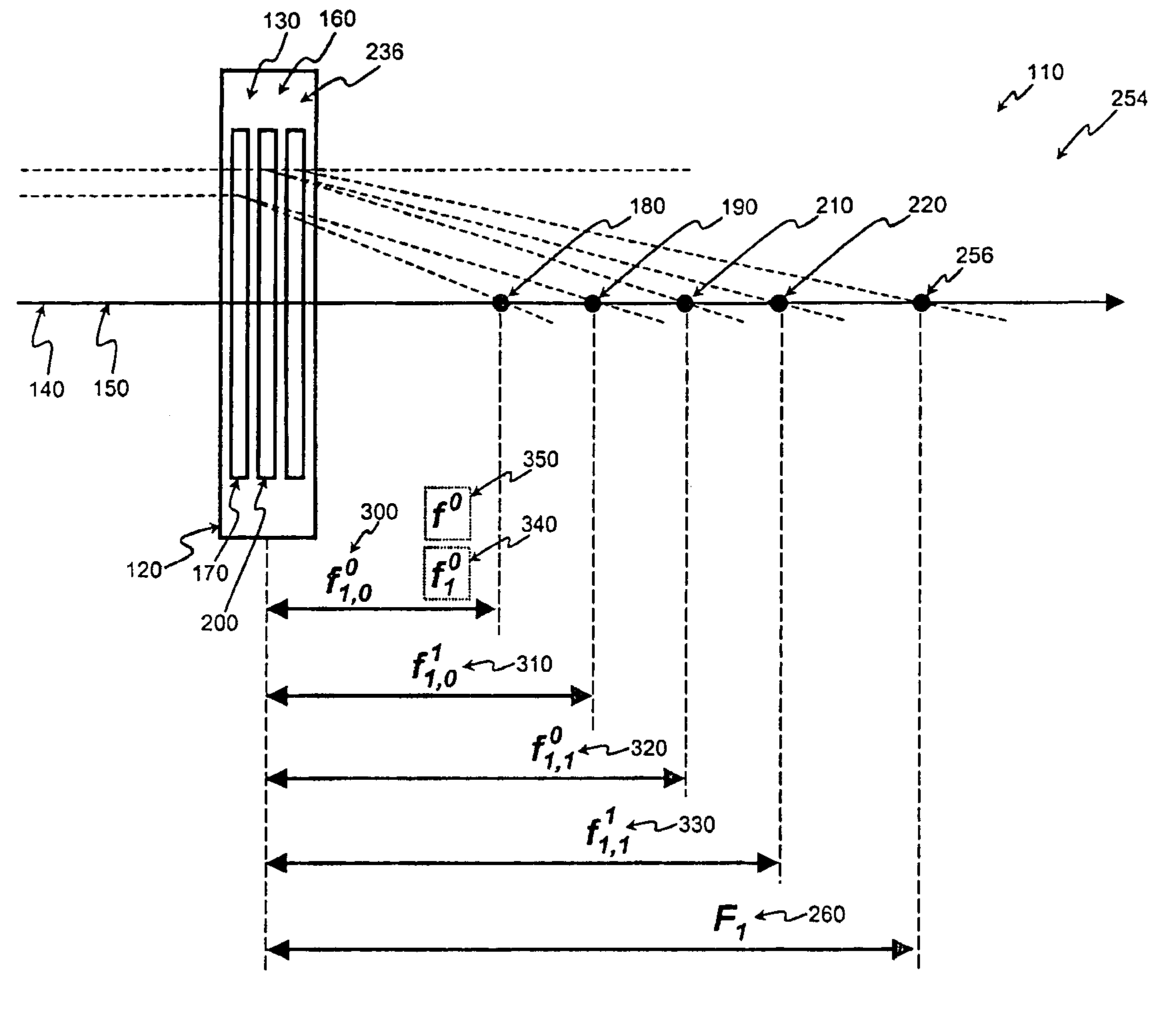
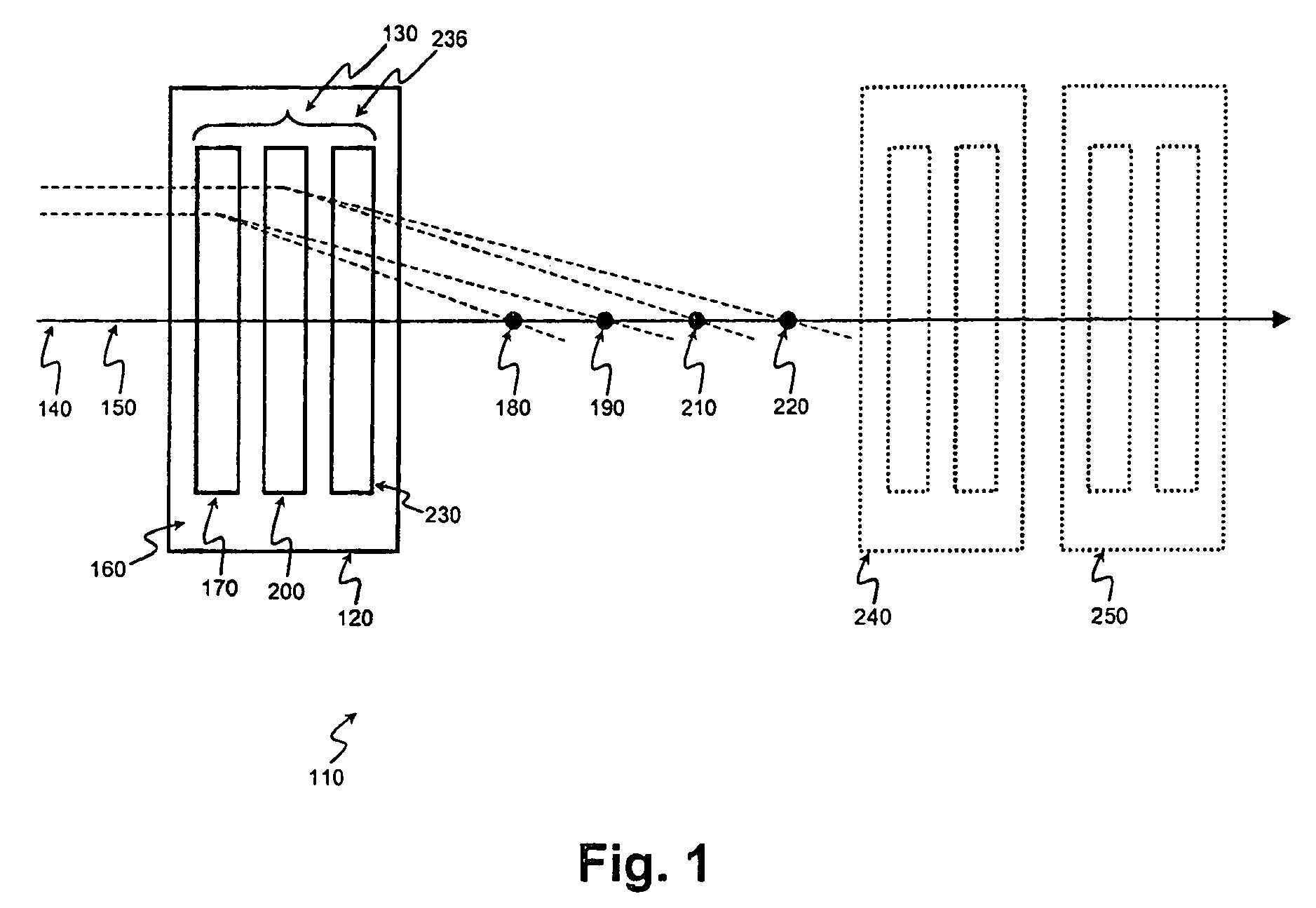
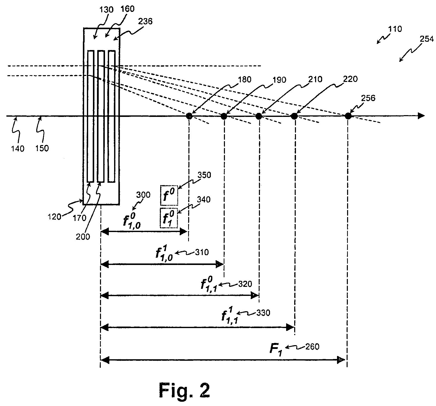
[0016]According to an embodiment of the present invention digital focus lens system may include a stack of switchable lens elements. The stack may include a plurality of optically transparent substrates symmetrically spaced apart, optically transparent electrodes deposited on the surfaces of each substrate, polymer layers deposited on the electrodes, and liquid crystal (LC) layers filling the gaps between adjacent pairs of polymer layers. Each polymer layer may be spatially patterned to provide a selected lens function having a selected focal length, ...


PUM

PropertyMeasurementUnit
lengthsaaaaaaaaaa
opticalaaaaaaaaaa
optical lossesaaaaaaaaaa

Abstract

A digital focus lens systems that can provide an optical system with a plurality of selectable focal powers is described. The system includes a number of switchable elements, each of which is capable of being switched between a first state and a second state, whereby the states represent unique focal powers. The switchable elements may be arranged coaxially in a stack such that each of them may contribute to a cumulative focal power of the system. If, for example, the system includes two such switchable elements, four focal powers for the lens system may be selected by appropriate choice the states of each switchable element. Digital telescopes, cameras, microscopes, and other optical instruments may be implemented using such digital focus lens systems. Methods of fabricating switchable elements and methods of controlling digital lens systems are also disclosed.

Description

[0001]This application is a continuation of U.S. patent application Ser. No. 10 / 617,572, filed Jul. 11, 2003, now U.S. Pat. No. 7,072,086, and published as U.S. Patent Application Publication 2004 / 0114203 A1, the entire disclosures of which are incorporated herein by reference. Application Ser. No. 10 / 617,572 claims the benefit of U.S. Provisional Patent Application No. 60 / 395,849 filed Jul. 11, 2002, the entire disclosures of which are incorporated herein by reference. This application is also a continuation-in-part of co-pending U.S. patent application Ser. No. 10 / 029,399 filed Oct. 19, 2001 and published as U.S. Patent Application Publication 2002 / 0158866 A1, the entire contents of which are incorporated herein by reference. Application Ser. No. 10 / 029,399 claims the benefit of US Provisional Application 60 / 242,395 filed Oct. 20, 2000, the entire disclosures of which are incorporated herein by reference. This application claims the benefit of priority of application Ser. Nos. 10 / ...

Claims


Application Information

Patent Timeline
Patent Type & Authority Patents(United States)
IPC IPC(8): G02B5/32G02BG02B3/14G02F1/29G03H1/02
CPCG02B3/14G02B5/1876G02B5/32G02F1/29G02F1/1347G02F2001/294G02F1/294
Inventor BATCHKO, ROBERT G.
Owner BATCHKO ROBERT G
Why Eureka
Try Eureka