Overload current protection device using magnetic impedance element

a protection device and magnetic impedance element technology, applied in galvano-magnetic devices, emergency protection arrangements for limiting excess voltage/current, emergency protection for supplying operative power, etc., can solve the problem of system misarrangement state for a long time, failure to obtain a wide current detection range, and inability to achieve wide current detection rang

Inactive Publication Date: 2007-05-15
FUJI ELECTRIC FA COMPONENTS & SYST CO LTD
View PDF30 Cites 5 Cited by
  • Summary
  • Abstract
  • Description
  • Claims
  • Application Information

AI Technical Summary

Benefits of technology

[0011]In yet another embodiment of the invention, two magnetic impedance elements are arranged in the positions in which the absolute values of the output in response to the magnetic flux generated by a current can be equal and the polarity can be opposite to each other, and the current can be detected from the calculation result of the difference between the outputs of the two magnetic impedance elements, or two magnetic impedance elements are arranged in the positions in which the absolute values of the output in response to the magnetic flux generated by a current can be equal and the polarity can be the same, and the current can be detected from the calculation result of the difference between the outputs of the two magnetic impedance elements.

Problems solved by technology

However, in the system using the switch, it is difficult to adjust a current when the switch enters the OFF state, and there arises the problem that the system is in the misarrangement state for a long time.
However, since this electronic system requires a complicated circuit, and a number of parts such as a constant voltage power source, etc. are required to operate a contact system by appropriately detecting a current.
Furthermore, a current detection transformer (what is called a CT) is used as current detection unit, which causes the problem that a wide current detection range cannot be obtained because the iron core generates magnetic saturation.
However, since it has low sensitivity, it requires an iron core, thereby failing in obtaining a wide current detection range as in the case of the above-mentioned CT.
Additionally, since the magnetoresistive element has a large fluctuation depending on the temperature and a large difference among the elements, and is subject to an influence of disturbance noise, there occurs the problem that high-precision device means requires a high cost.

Method used


Image

  • Overload current protection device using magnetic impedance element
  • Overload current protection device using magnetic impedance element
  • Overload current protection device using magnetic impedance element

Examples


Embodiment Construction

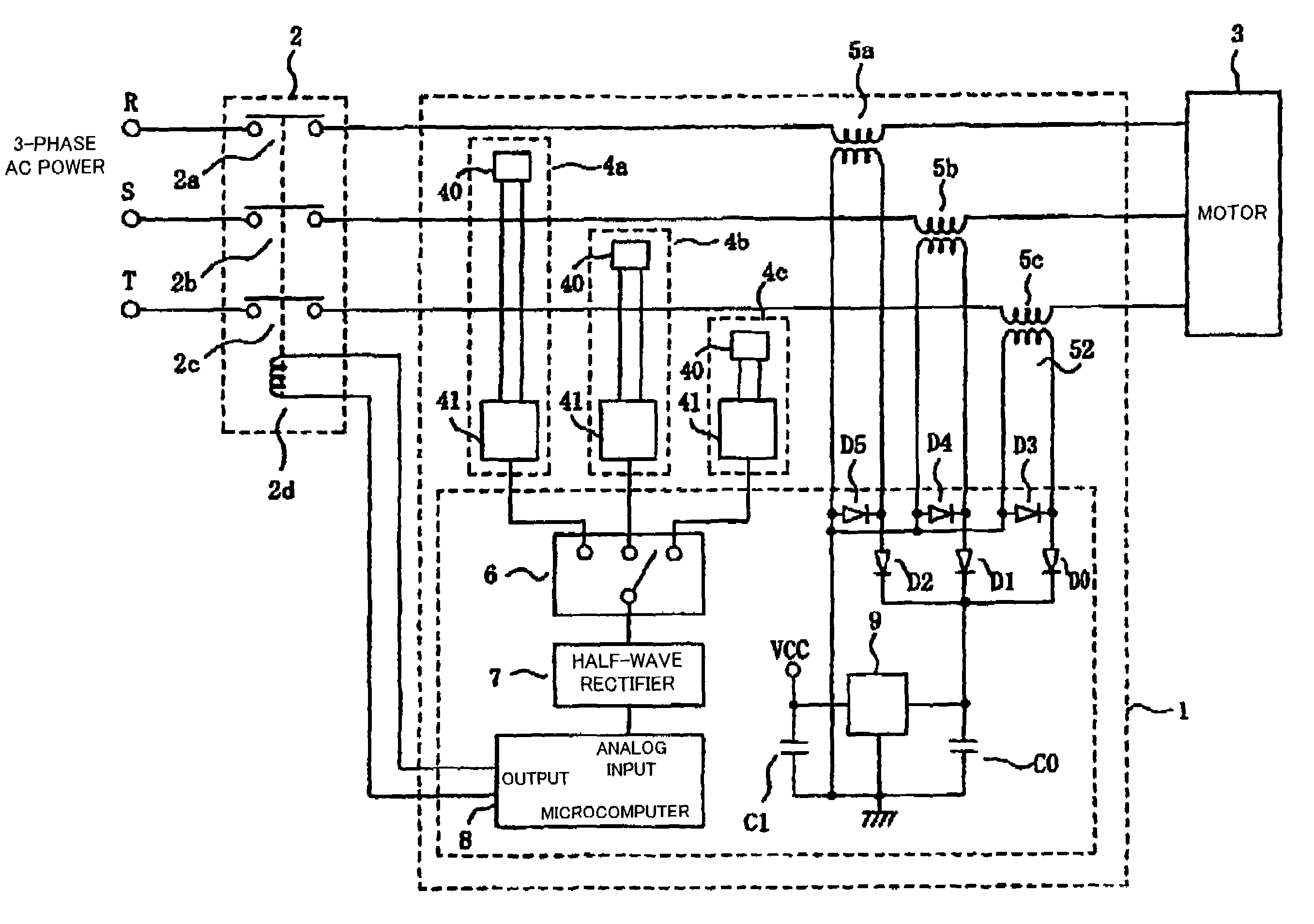
[0029]FIG. 1 shows the configuration of the system showing an embodiment of the present invention.

[0030]Reference characters R, S, and T denote power supply lines connected to a 3-phase AC power source not shown in the attached drawings, and are connected to a motor 3 through a 3-phase contactor (switch) 2 and three power supply transformers 5a, 5b, and 5c. Current detectors 4a, 4b, and 4c are arranged for each phase between the 3-phase contactor 2 and the three power supply transformers 5a, 5b, and 5c. The contactor 2 includes contact points 2a, 2b, and 2c each of which is coupled to the motor 3 through the primary winding of respective power supply transformers 5a, 5b, and 5c by the different power supply lines. The set of contact points is mechanically coupled for simultaneous operation by an electromagnetic coil 2d. The electromagnetic coil 2d is connected to the digital output of a microcomputer 8. A control circuit including the microcomputer 8, the current detectors 4a, 4b, a...


PUM


Abstract

An overload current protection device for cutting off power applied from a power supply to a load (3) such as a motor by means of a contactor (switch) (2) at overloading. With the configuration, an element (40) having a magnetic impedance effect as current detection units (4a, 4b, 4c) is used to thereby expand a current detection range by eliminating magnetic saturation due to a core, a problem with a conventional current transformer, thereby providing at low costs an overload current protection device having a wide current detection range.

Description

TECHNICAL FIELD[0001]The present invention relates to an overload current protection device for detecting a current flowing through a conductor, and cutting off the current when the current exceeds a predetermined threshold, for example, an overload current protection device capable of controlling the supply of power to a motor.BACKGROUND ART[0002]Normally, for example, an overload current protection device of this type detects that the current flowing to a 3-phase motor through a contactor exceeds a safe threshold, and cuts off the current to the motor depending on the detection result, which has been realized by making all or a part the current of the motor flow through a bimetallic element. That is, if a current is applied to the switch made of a bimetal, the bimetal is heated depending on the current magnitude, and the motor current exceeds a safe threshold for a predetermined time, then the bimetal is bent by heat and a switch connection point is set in an OFF state, and the cu...

Claims


Application Information

Patent Timeline
Patent Type & Authority Patents(United States)
IPC IPC(8): H02H3/08G01R33/02H01L43/00H02H1/00H02H1/04H02H1/06H02H7/085H02P23/00H02P23/07H02P25/10
CPCG01R33/02H02H1/0007H02H1/043H02H1/06H02H7/085
Inventor KUDO, TAKAHIROKITAIDE, YUJIROISHIKAWA, KIMITADA
Owner FUJI ELECTRIC FA COMPONENTS & SYST CO LTD
Why Eureka
Try Eureka