Locking arrangement for a cover part of a subscriber terminal device

a terminal device and locking arrangement technology, applied in the direction of telephonic communication, telephonic set construction, electrical apparatus, etc., can solve the problems of excessive clearance between the cover and the rest of the device structure, increase naturally, and press the accumulator with a sufficient force, etc., to achieve the effect of easy locking of the cover, easy opening and simple structure of the locking devi

a terminal device and locking arrangement technology, applied in the direction of telephonic communication, telephonic set construction, electrical apparatus, etc., can solve the problems of excessive clearance between the cover and the rest of the device structure, increase naturally, and press the accumulator with a sufficient force, etc., to achieve the effect of easy locking of the cover, easy opening and simple structure of the locking devi

US7218731B2Inactive Publication Date: 2007-05-15FLEXTRONICS SALES & MARKETING A P

Image

  • Locking arrangement for a cover part of a subscriber terminal device
  • Locking arrangement for a cover part of a subscriber terminal device
  • Locking arrangement for a cover part of a subscriber terminal device

Examples


Embodiment Construction

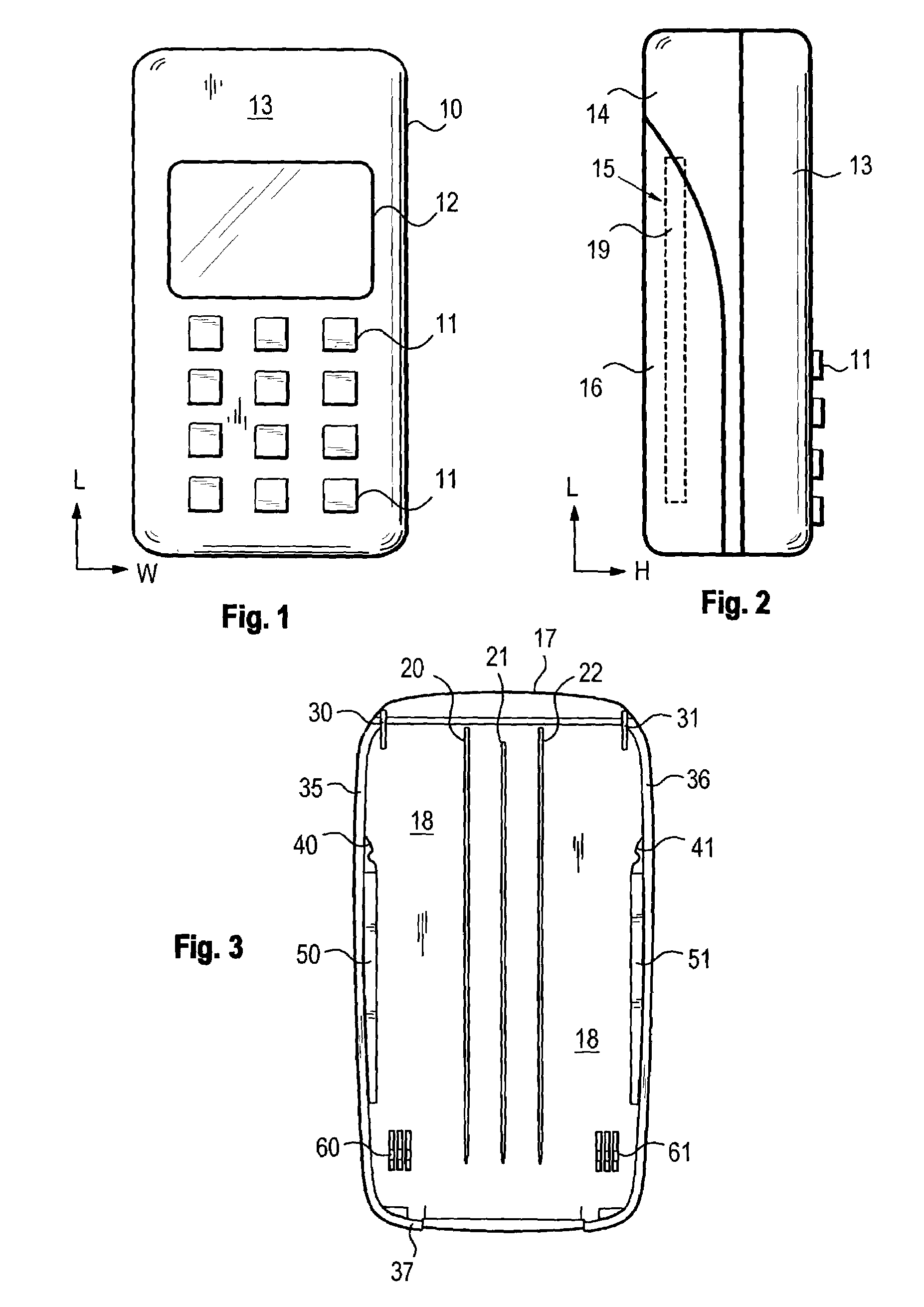
[0026]FIG. 1 shows a typical subscriber terminal device as seen from the front. The subscriber terminal device shown in the figure is a mobile station 10, which comprises among other things keys 11 and a display 12. Of the cover or enclosure structure of the terminal device, one can see in the figure the front cover, i.e. a so-called A cover 13. The cover structure may be e.g. plastic, fiberglass or metal.

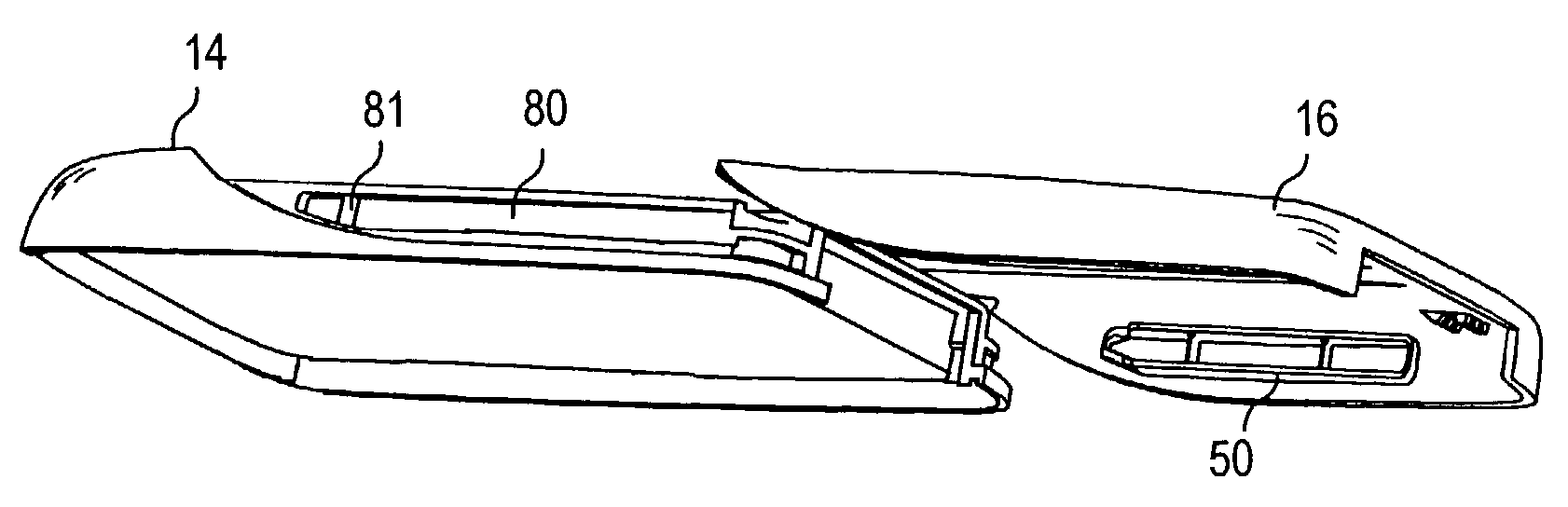
[0027]FIG. 2 shows the subscriber terminal device as seen from the side, in which case the cover structure can be better seen. In addition to the front cover, the subscriber terminal device comprises a rear part, i.e. a so-called B cover 14, in which one has formed an accumulator space 15 for the accumulator 19. The presented subscriber terminal device comprises, in addition, an accumulator cover 16 for closing the accumulator space 15. The accumulator space is thus formed in between the B cover and the accumulator cover. Since hereinafter, a reference is made to the different dire...


PUM


Abstract

The present invention relates to a locking arrangement for a cover structure of a portable terminal device of a telecommunication system. The cover structure comprises at least one frame part (14), a cover part (16) connected to the frame part that can be removed from the frame part by the user, and locking elements for attaching the cover part to the frame part. In order that one could achieve a secure attachment and locking for the accumulator cover or accumulator packet of the device that at the same time enables the eliminating of the excessive clearances between the can parts, the locking elements comprise, in the frame part and cover part, slide bars (50, 51) and slide grooves (80) corresponding to each other.

Description

TECHNICAL FIELD OF THE INVENTION[0001]The invention relates to attachment and locking of a removable cover part of a terminal device, particularly a portable subscriber terminal device of a telecommunication system, such as an accumulator cover or accumulator packet, to the rest of the device structure of the subscriber terminal device.BACKGROUND OF THE INVENTION[0002]The body of a subscriber terminal device such as e.g. a mobile station typically comprises two cover parts, a so-called A cover and a B cover, of which the A cover forms the front part of the device body and the B cover the rear part of the body. In addition, the device comprises some kind of cover or corresponding for closing the battery space in other words the accumulator space of the device. The accumulator may also be integrated into the cover, in which case one speaks about a so-called accumulator packet. In that case, there is no separate cover in the device; instead the accumulator packet forms a part of the ou...

Claims


Application Information

Patent Timeline
15 May 2007
Publication
US7218731B2
IPC
H04M1/02; H04B1/38
CPC
H04M1/0262
Inventors
TURUNEN, HARRI