Thermal-type flow rate sensor and manufacturing method thereof

a flow rate sensor and flow rate technology, applied in the direction of volume/mass flow measurement, measurement devices, instruments, etc., can solve the problems of measuring error generation and measurement error generation, and achieve the effect of reducing measurement error and reducing nois

Active Publication Date: 2007-05-22
DENSO CORP
View PDF3 Cites 27 Cited by
  • Summary
  • Abstract
  • Description
  • Claims
  • Application Information

AI Technical Summary

Benefits of technology

[0009]In view of the above-described problems, it is an object of the present invention to provide a thermal-type flow rate sensor and its manufacturing method, which can reduce noises caused by a turbulent flow and reduce a measuring error.
[0010]According to an aspect of the present invention, a thermal-type flow rate sensor includes: a flow rate detecting chip that includes a substrate having a thin wall portion, and a flow rate detecting portion having a heater located in the thin wall portion; a circuit chip electrically connected to the flow rate detecting portion through a first connecting wire and having a circuit portion for controlling input and output of the flow rate detecting portion; a lead portion electrically connected to the circuit portion through a second connecting wire; a support member having a groove portion in which the flow rate detecting chip is attached; and a mold material. The mold material is formed through a mold forming, to integrally cover a predetermined range including the circuit chip, connecting parts of the first connecting wire with the flow rate detecting portion and the circuit portion, and connecting parts of the second connecting wire with the circuit portion and the lead portion, so as to expose a part of the flow rate detecting portion including the heater to a measured fluid. The flow rate detecting chip is located in the groove portion of the support member to have a clearance with the groove portion and to form a cavity part inside the thin wall portion, and the cavity part communicates with an outside of the thin wall portion through a communicating portion that includes the clearance. Furthermore, the clearance is blocked by a filler material at least at a portion positioned in the predetermined range, and the filler material prevents the mold material from entering the clearance in the mold forming.
[0011]Accordingly, the cavity part of the flow rate detecting chip positioned and arranged in the groove portion of the support member is not directly exposed to the measured fluid. Therefore, noises due to a turbulent flow can be reduced in comparison with a structure in which no support member is arranged. In addition, the cavity part inside the thin wall portion of the substrate is not completely blocked by the support member and communicates with the exterior of the flow rate detecting chip through the communicating portion formed in the support member. However, in this invention, the clearance is blocked by the filler material at least at a portion positioned in the predetermined range, and the filler material prevents the mold material from entering the clearance in the mold forming. Accordingly, it can prevent the mold material from entering to the cavity part and the cavity part from being blocked.
[0013]Further, the support member and the lead portion can be made of the same material. In this case, the structure of the flow rate sensor can be made simple. Furthermore, a semiconductor substrate can be used as the substrate.
[0014]The communicating portion further includes a communication groove that is provided in the support member to communicate with the clearance. Furthermore, the communication groove can be made to communicate with the clearance between a side wall of the flow rate detecting chip and the groove portion opposite to the side wall. Therefore, it can prevent a large amount of the measured fluid such as air from entering to the cavity part, and noise due to the flow of the measured fluid can be effectively reduced. Furthermore, a part of the groove portion can be used as a staying portion in which the filler material is provided.
[0016]According to another aspect of the present invention, a method of manufacturing a thermal-type flow rate sensor includes: arranging a flow rate detecting chip in a groove portion of a support member to form a clearance with the groove portion, wherein the flow rate detecting chip includes a substrate having a thin wall portion, and a flow rate detecting portion having a heater located in a cavity part inside the thin wall portion; electrically connecting the flow rate detecting chip with a circuit chip and a lead portion using connecting wires; injecting a filler material into the clearance to block at least a part of the clearance; and integrally molding a mold material to integrally cover a predetermined range including the circuit chip and connection parts of the connecting wires, to expose a part of the flow rate detecting portion including the heater to a measured fluid. Furthermore, the clearance is blocked at least in an area positioned within the predetermined range such that the mold material is prevented to entering the clearance in the integrally molding. Therefore, the method can prevent the mold material from entering to the cavity part inside the thin wall portion.

Problems solved by technology

Accordingly, when a circumferential portion of the cavity part is fixed (e.g., adhered) to the support member so as to surround the cavity part of the substrate, it is difficult for the temperature of the fluid (air) sealed in the cavity part to follow a temperature change around the thermal-type flow rate sensor, and a measuring error is generated.
Accordingly, the cavity part is blocked by this mold material, and the measuring error is generated.

Method used


Image

  • Thermal-type flow rate sensor and manufacturing method thereof
  • Thermal-type flow rate sensor and manufacturing method thereof
  • Thermal-type flow rate sensor and manufacturing method thereof

Examples


first embodiment

(First Embodiment)

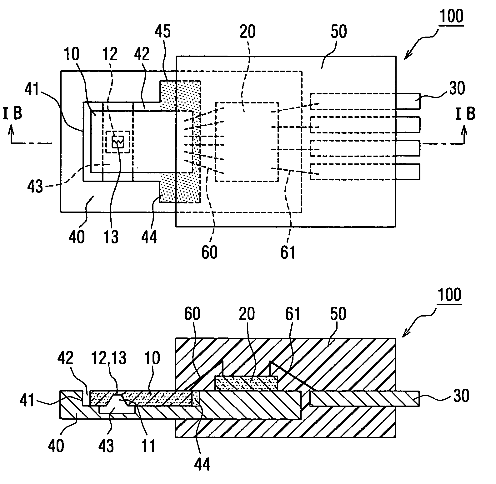
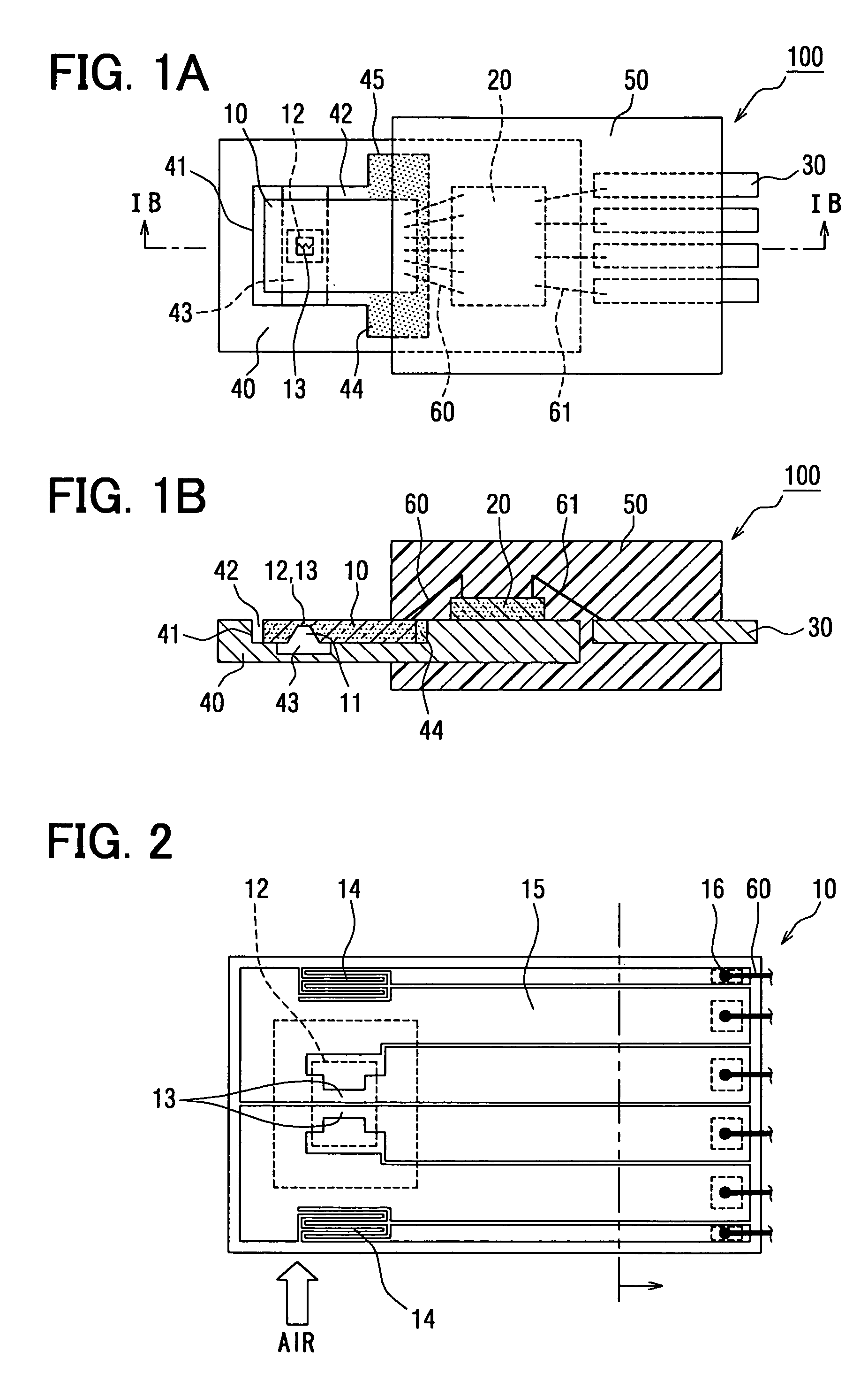
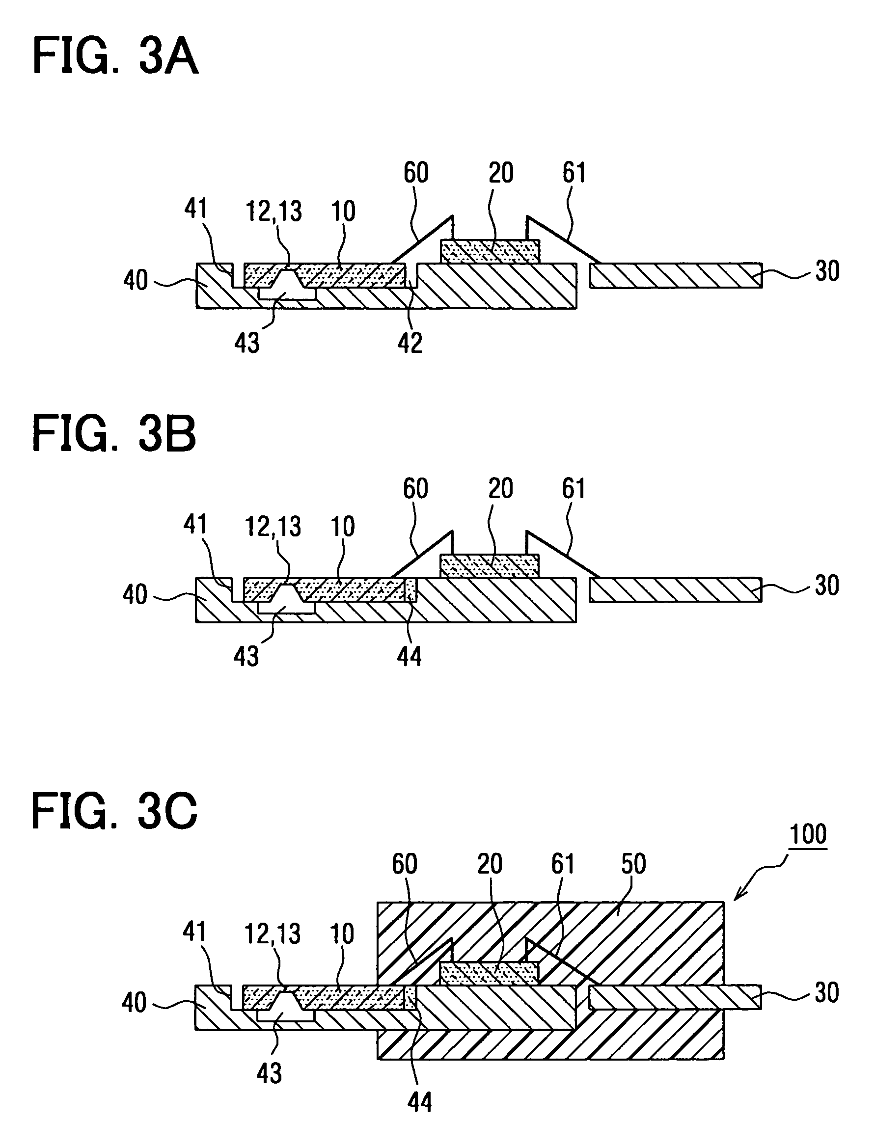
[0025]As shown in FIGS. 1A and 1B, a thermal-type flow rate sensor 100 in this embodiment is constructed with a flow rate detecting chip 10 partially exposed to a measured fluid (e.g., air, in this embodiment) and detecting its flow rate, a circuit chip 20 for controlling the input and output of the flow rate detecting chip 10, leads 30 electrically connected to the circuit chip 20 and connected to the exterior, a support member 40 for mounting at least the flow rate detecting chip 10, and a mold material 50. The mold material 50 is molded using a resin material, for example, for integrally covering a part of the flow rate detecting chip 10, the circuit chip 20 and a part of the leads 30. In FIGS. 1A and 1B, reference numerals 60 and 61 respectively designate bonding wires for electrically connecting the flow rate detecting chip 10 and the circuit chip 20, and bonding wires for electrically connecting the circuit chip 20 and the leads 30.

[0026]For example, the flow...

second embodiment

(Second Embodiment)

[0047]Next, the second embodiment of the present invention will be described with reference to FIGS. 4A, 4B and FIGS. 5A to 5C.

[0048]A thermal-type flow rate sensor 100 and its manufacturing method in the second embodiment have common portions to the first embodiment. Accordingly, detailed explanations of the common portions are omitted and different portions will be mainly described.

[0049]In the thermal-type flow rate sensor 100 of this embodiment, as shown in FIGS. 4A, 4B, the support member 40 for mounting at least the flow rate detecting chip 10 is constructed with a first support member 40a and a second support member 40b.

[0050]For example, the first support member 40a is formed by the same material as leads 30, and a through hole 46 able to arrange the flow rate detecting chip 10 is formed instead of the groove portion 41 in the first embodiment. In this embodiment, the thickness of the first support member 40a is approximately equal to that of the flow rat...


PUM


Abstract

In a thermal-type flow rate sensor, a mold material is formed to integrally cover a predetermined range including a circuit chip, connecting parts of connecting wires with a flow rate detecting chip and the circuit chip, and connecting parts of connecting wires with the circuit chip and a lead portion, to expose a part of the flow rate detecting chip to a measured fluid. The flow rate detecting chip is located in a groove portion of a support member to have a clearance with the groove portion and to form a cavity part inside a thin wall portion of the detecting chip. The cavity part communicates with an outside through a communicating portion that includes the clearance, and the clearance is blocked by a filler at least at a portion positioned in the predetermined range. Therefore, the filler prevents the mold material from entering the clearance in the mold forming.

Description

CROSS REFERENCE TO RELATED APPLICATION[0001]This application is based on Japanese Patent Application No. 2004-277794 filed on Sep. 24, 2004, the contents of which are incorporated herein by reference in its entirety.FIELD OF THE INVENTION[0002]The present invention relates to a thermal-type flow rate sensor and a method for manufacturing the thermal-type flow rate sensor.BACKGROUND OF THE INVENTION[0003]For example, a thermal-type flow rate sensor described in JP-B2-3328547 detects a flow rate of a fluid by utilizing the fact that heat caused by a heater is robbed by the fluid passing the vicinity of the heater.[0004]The thermal-type flow rate sensor in JP-B2-3328547 includes a flow rate detecting chip, a circuit chip, leads and a support member. The flow rate detecting chip has a flow rate detecting portion including a heater (heat generating resistor) formed in a thin wall portion of a semiconductor substrate. The circuit chip has a circuit portion electrically connected to the fl...

Claims


Application Information

Patent Timeline
Patent Type & Authority Patents(United States)
IPC IPC(8): G01F1/68
CPCG01F1/6845G01F1/688
Inventor TANAKA, MASAAKIMIZUNO, TIAKIARIYOSHI, HIROMI
Owner DENSO CORP
Why Eureka
Try Eureka