Permanent downhole deployment of optical sensors

a technology of optical sensors and deployment methods, applied in the field of oil and gas wellbores, can solve the problems of complex maneuvers and equipment, sensor deployments on production tubing that do not allow monitoring of wellbore and formation conditions during, and measurement of formation parameters that derive some inaccuracy,

Inactive Publication Date: 2007-05-22
WEATHERFORD TECH HLDG LLC
View PDF48 Cites 98 Cited by
  • Summary
  • Abstract
  • Description
  • Claims
  • Application Information

AI Technical Summary

Benefits of technology

[0017]In one aspect, the present invention involves an apparatus for permanently measuring wellbore or formation parameters, comprising a casing string permanently located within a wellbore, and at least one optical sensor attached to the casing string, the at least one optical sensor capable of measuring one or more wellbore or formation parameters. In another aspect, the present invention provides an apparatus for permanently measuring wellbore or formation parameters, comprising a casing string permanently located within a wellbore, and at least one optical sensor located at least partially within a wall of the casing string, the at least one optical sensor capable of measuring one or more wellbore or formation parameters.
[0018]In yet another aspect, the present invention provides a method of permanently monitoring wellbore or formation parameters, comprising providing a casing string having at least one optical sensor attached thereto, locating the casing string within a wellbore, and measuring one or more wellbore or formation parameters with the at le

Problems solved by technology

While optical sensors placed on production tubing allow measurements while the production tubing is located within the wellbore, the sensors on production tubing do not allow monitoring of wellbore and formation conditions during the drilling and well completion operations and after the production tubing is removed from the wellbore.
Furthermore, when employing seismic sensors which need to be coupled

Method used


Image

  • Permanent downhole deployment of optical sensors
  • Permanent downhole deployment of optical sensors
  • Permanent downhole deployment of optical sensors

Examples


Embodiment Construction

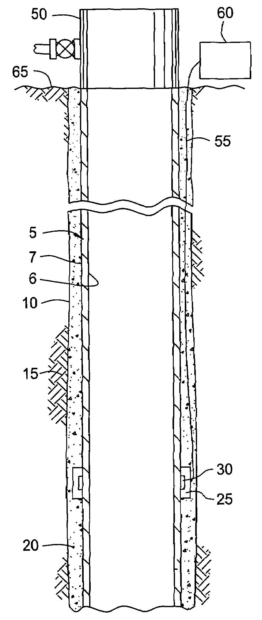
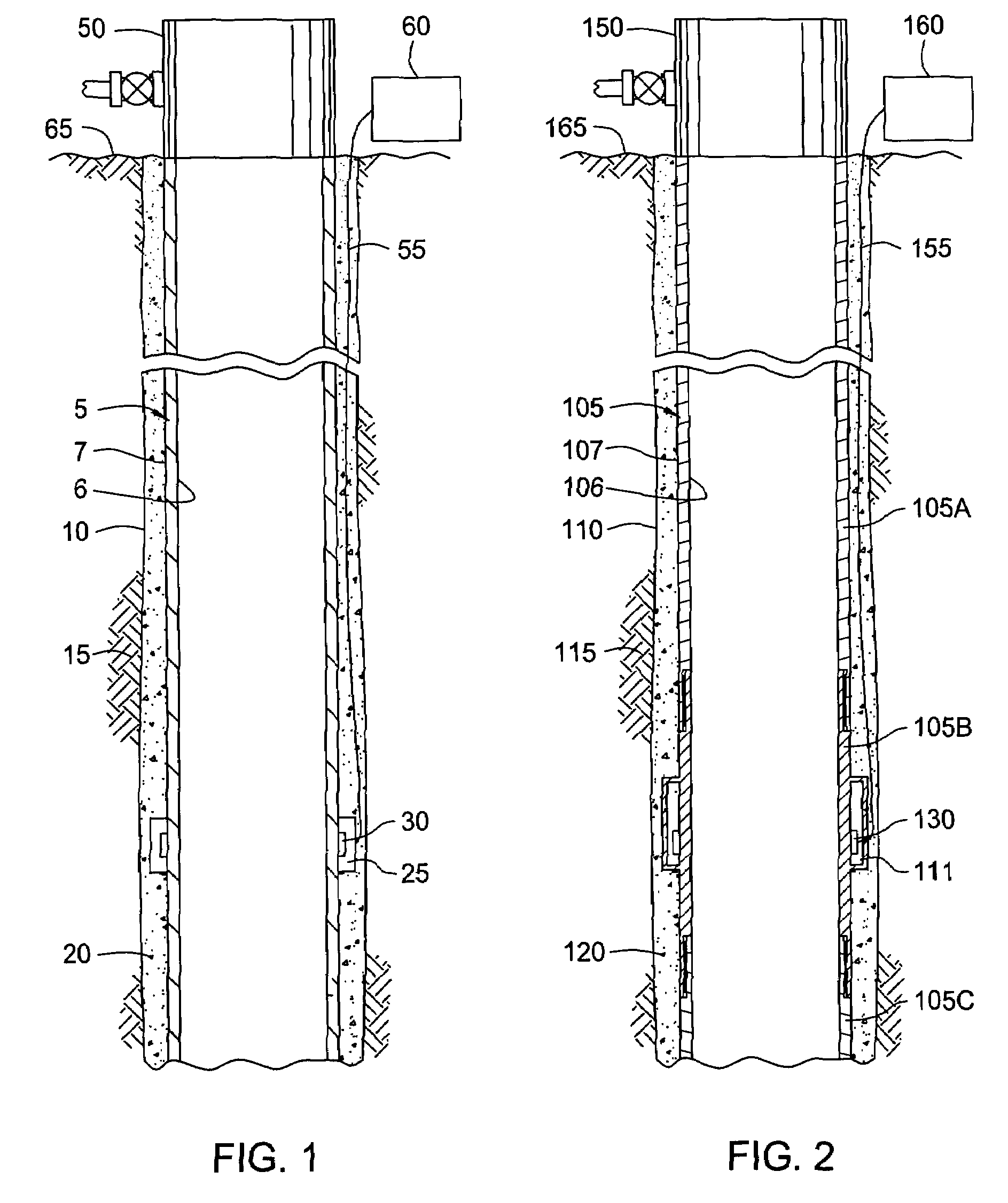
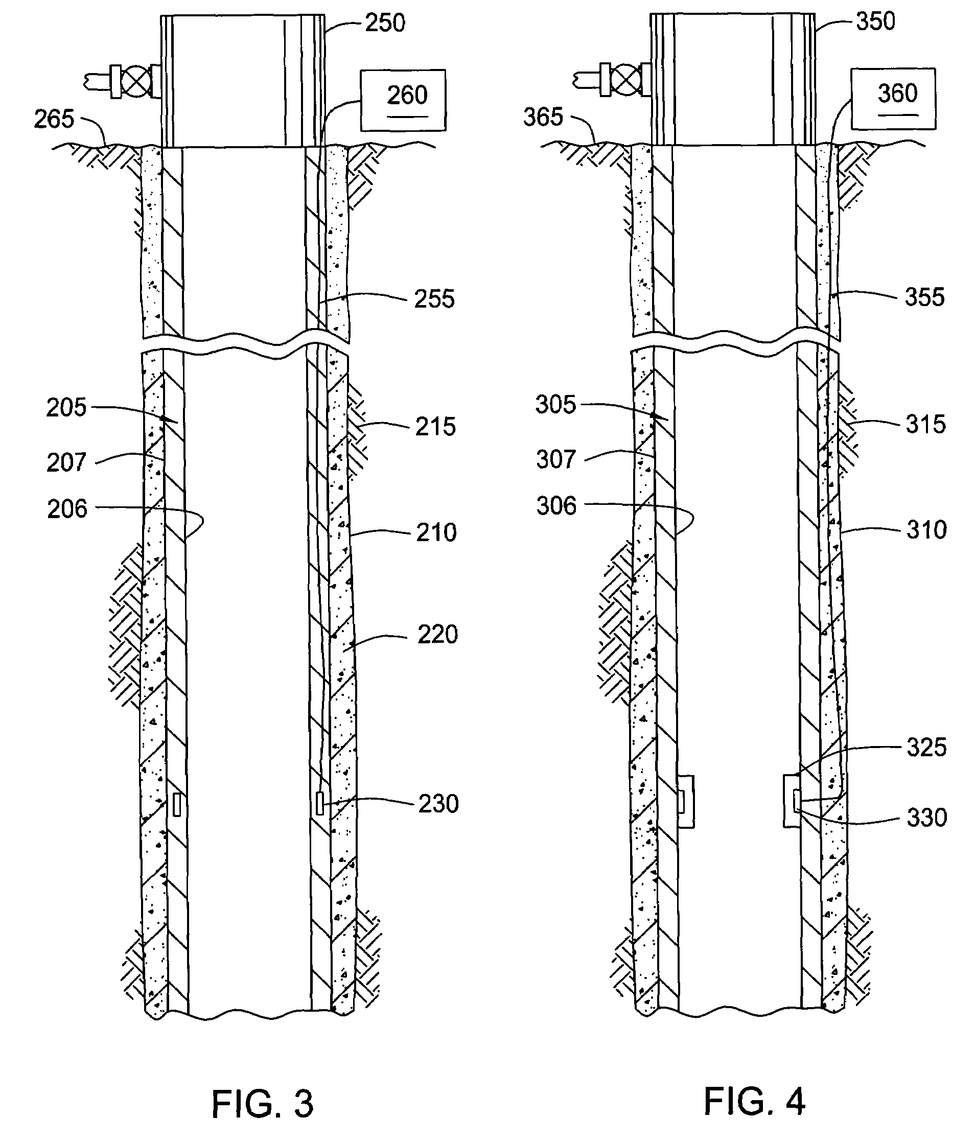
[0028]In contrast to the current practice of deploying sensors during production operations with production tubing, the present invention provides apparatus and methods for permanently deploying optical sensors for use in measuring wellbore parameters during all wellbore operations, including but not limited to completion operations, drilling operations, and intervention operations. The present invention also beneficially provides methods and apparatus for placing optical sensors within the wellbore earlier in the wellbore operations, specifically during drilling and completion of the well, which occur prior to production operations. Additionally, the present invention includes apparatus and methods for locating seismic sensors closer to the formation than is possible with the current use of production tubing for the deployment of optical sensors, by use of one or more optical sensors deployed with a casing string. Although pressure and temperature sensing does not require coupling ...


PUM


Abstract

The present invention involves methods and apparatus for permanent downhole deployment of optical sensors. Specifically, optical sensors may be permanently deployed within a wellbore using a casing string. In one aspect, one or more optical sensors are disposed on, in, or within the casing string. The optical sensors may be attached to an outer surface of the casing string or to an inner surface of the casing string, as well as embedded within a wall of the casing string. The optical sensors are capable of measuring wellbore parameters during wellbore operations, including completion, production, and intervention operations.

Description

CROSS-REFERENCE TO RELATED APPLICATIONS[0001]This application is a continuation-in-part of co-pending U.S. patent application Ser. No. 10 / 288,229, filed Nov. 5, 2002, which is herein incorporated by reference in its entirety.[0002]This application is related to co-pending U.S. patent application Ser. No. 10 / 677,135, filed on the same day as the current application, entitled “Instrumentation for a Downhole Deployment Valve”, which is herein incorporated by reference in its entirety.BACKGROUND OF THE INVENTION[0003]1. Field of the Invention[0004]The present invention generally relates to methods and apparatus for use in oil and gas wellbores. More particularly, the invention relates to using instrumentation to monitor downhole conditions within wellbores.[0005]2. Description of the Related Art[0006]In well completion operations, a wellbore is formed to access hydrocarbon-bearing formations by the use of drilling. Drilling is accomplished by utilizing a drill bit that is mounted on the...

Claims


Application Information

Patent Timeline
IPC IPC(8): E21B47/12E21B21/00E21B21/08E21B21/10E21B34/00E21B34/06E21B34/10E21B47/10
CPCE21B21/08E21B34/06E21B34/101E21B47/06E21B47/10E21B47/122E21B47/123E21B47/14G01V1/40E21B2021/006E21B2034/005E21B21/085E21B2200/05E21B47/135E21B47/13E21B47/114
Inventor BOSTICK, III, F. X.HOSIE, DAVID G.GRAYSON, MICHAEL BRIANBANSAL, R. K.
Owner WEATHERFORD TECH HLDG LLC
Why Eureka
Try Eureka