Electric actuator

Active Publication Date: 2007-05-22
SMC CORP
View PDF20 Cites 14 Cited by
  • Summary
  • Abstract
  • Description
  • Claims
  • Application Information

AI Technical Summary

Benefits of technology

[0022]A general object of the present invention is to provide an electric actuator provided with a tension-adjusting mechanism which makes it

Problems solved by technology

As a result, it is difficult to correctly

Method used


Image

  • Electric actuator
  • Electric actuator
  • Electric actuator

Examples


first embodiment

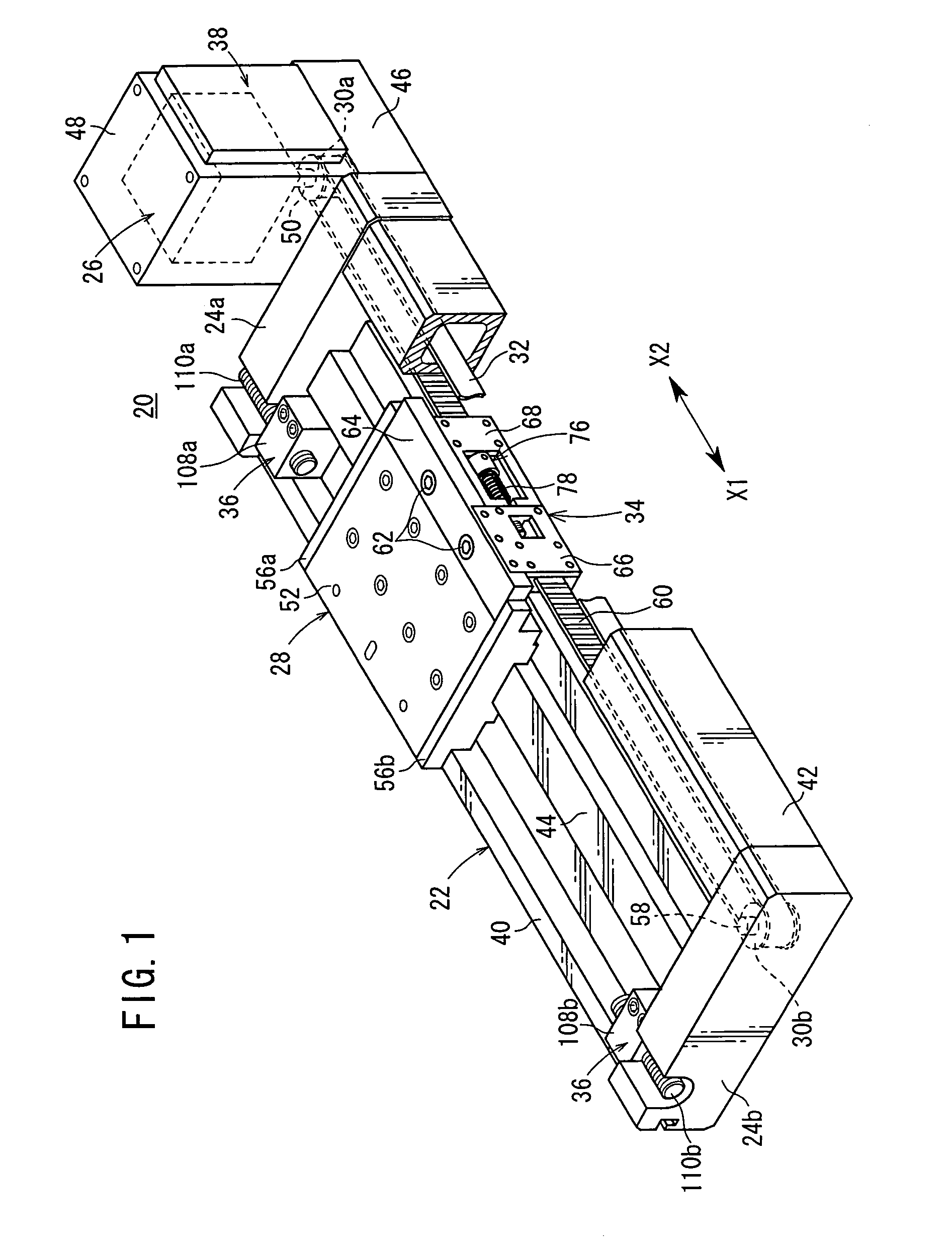
[0051]With reference to FIG. 1, reference numeral 20 indicates an electric actuator according to the present invention.

[0052]The electric actuator 20 comprises an elongate body 22, end blocks 24a, 24b which are integrally connected to both ends of the body 22, a rotary driving source 26 connected to one end block 24a and driven by an electric signal, a slider 28 for transporting a workpiece, and a timing belt (driving force-transmitting belt) 32 which transmits the driving force to the slider 28 via a gear section 30a fitted into the rotary driving source 26.

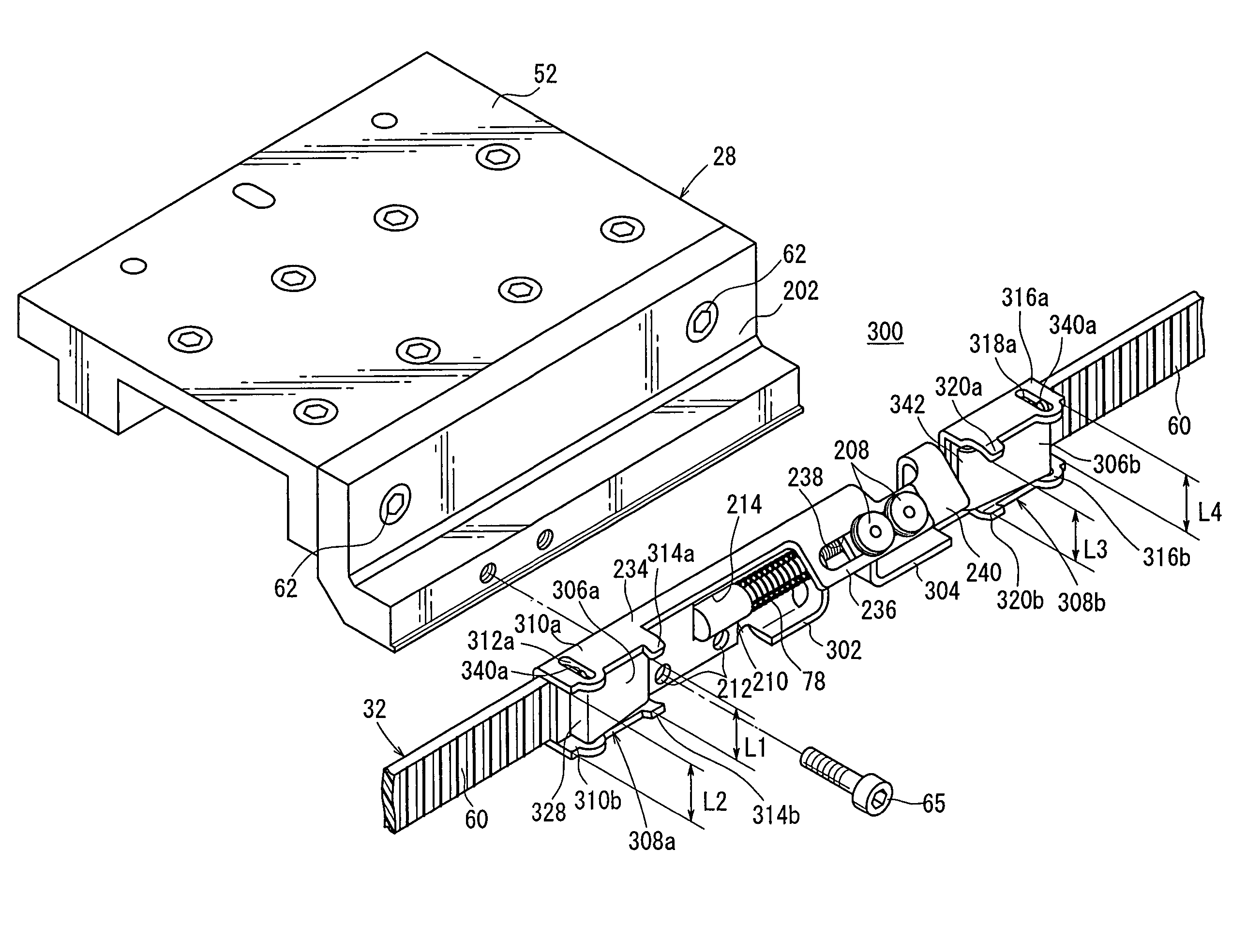
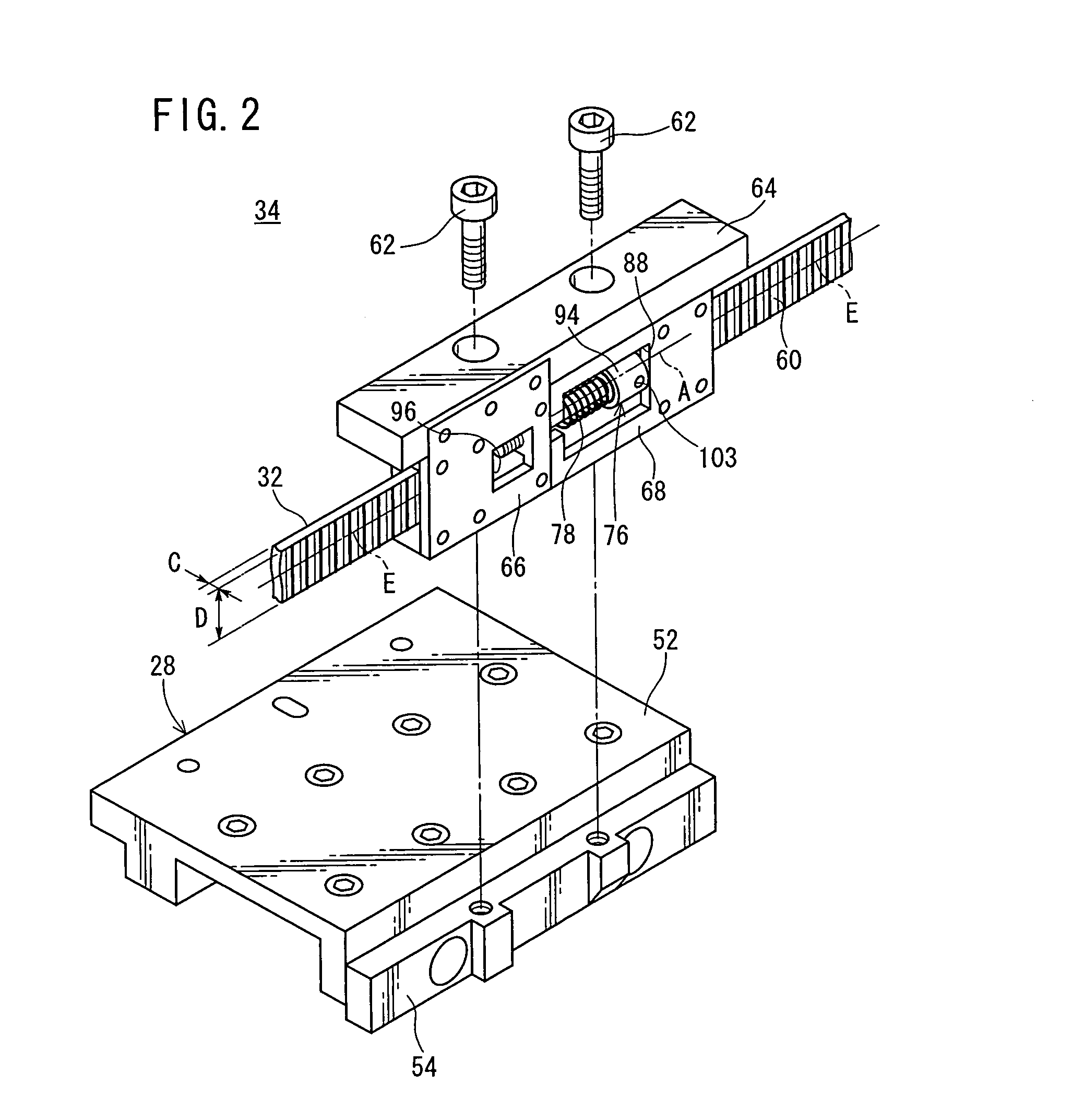
[0053]The electric actuator 20 further comprises a belt-adjusting mechanism (tension-adjusting mechanism) 34 which adjusts the tension of the timing belt 32, stopper mechanisms 36 which regulate the displacement amount of the slider 28, and a control panel 38 which is used to control the electric actuator 20.

[0054]The body 22 includes a main frame 40 which is arranged in the axial direction, a hollow subframe 42 which is provide...


PUM


Abstract

An electric actuator comprises a rotary driving source, a timing belt which is circled or orbited under the driving action of the rotary driving source, a slider which is displaced by the timing belt in the axial direction, and a belt-adjusting mechanism which is connected to a side surface of the slider. Both ends of the timing belt are connected to the belt-adjusting mechanism respectively. The tension of the timing belt is adjusted by rotating an adjusting screw of the belt-adjusting mechanism.

Description

BACKGROUND OF THE INVENTION[0001]1. Field of the Invention[0002]The present invention relates to an electric actuator comprising a driving force-transmitting belt for transmitting the rotary driving force of a rotary driving source to a slider so that the slider is moved.[0003]2. Description of the Related Art[0004]An electric actuator has been hitherto widely used as a means for transporting a workpiece or the like, in which a timing belt is driven by the rotary driving force of a rotary driving source such as a motor to displace a slider for transporting the workpiece.[0005]A tension-adjusting means is provided for the timing belt of a resin material in order to adjust the tension when the timing belt is loosened during the assembling or due to the use for many years.[0006]As the tension-adjusting means for the timing belt, for example, a pair of pulleys are used. The timing belt runs over the pulleys. The pulleys are displaced in directions to approach or separate from each other...

Claims


Application Information

Patent Timeline
IPC IPC(8): F16G7/06B23Q5/34F16H7/08F16H19/06
CPCB23Q5/34F16H7/08F16H19/06F16H19/0672Y10T74/18832F16H2007/088F16H2019/0686F16H2007/0806
Inventor IIDA, KAZUHIRO
Owner SMC CORP
Why Eureka
Try Eureka