Lighting control system and method

a control system and light control technology, applied in the field of light control systems, can solve the problems of system failure to operate, controllers with limited capabilities, communication bottlenecks, etc., and achieve the effect of cost-effectiveness

Inactive Publication Date: 2007-05-22
BRUCE AEROSPACE
View PDF15 Cites 134 Cited by
  • Summary
  • Abstract
  • Description
  • Claims
  • Application Information

AI Technical Summary

Benefits of technology

[0008]It is an object of the invention to provide an improved lighting control system and method wherein the fluorescent ballast, lighting controller, or power supply contains a microprocessor-based intelligence that allows the device to independently store, calculate, and execute complex lighting scenarios without the necessity for any type of external control architecture. This allows the system to be retrofit into existing lighting applications without the need for expensive platform or architectural reconfiguration. In this way, the system may provide a cost-effective solution for the retrofit or new installation of lighting systems, where dimming or mood lighting effects are desired. That is, the invention contemplates a distributed architecture.
[0010]Preferably, the microprocessor-based intelligence executes a script corresponding to the desired lighting scenario that directs the control of the lighting. The script is written in a lighting control scripting language that is a full-featured scripting language such that a script may direct the light controller and provide detailed control over the lighting environment.
[0011]At a more detailed level, the inclusion of a microprocessor-based intelligence within each lighting controller, relieves the control communication network of the necessity for continuous communication. Each lighting controller on the network only requires infrequent command scripts in order to execute complex lighting scenarios. According to this aspect of the invention, in the absence of any type of external control communications, each lighting controller in the system can continue to run its own script and control its own lamp or lamps. In this way, it is possible to overcome problems associated with communication bottlenecks an host disconnects. This also makes it possible to implement a number of different control strategies for the lighting controller, other than a serial communications bus control method.
[0012]Put another way, each light controller may independently store, calculate, and execute complex lighting scenarios without the necessity for any type of external control architecture due to the distributed architecture approach contemplated by the invention.

Problems solved by technology

One problem in such a system is that a bottleneck in the communications may occur as lights are turned on and brightness is adjusted.
Another problem in such a system is the failure of the system to operate when the host computer is disconnected.
These controllers have limited capabilities, and have only been used in certain applications.

Method used


Image

  • Lighting control system and method
  • Lighting control system and method
  • Lighting control system and method

Examples


Embodiment Construction

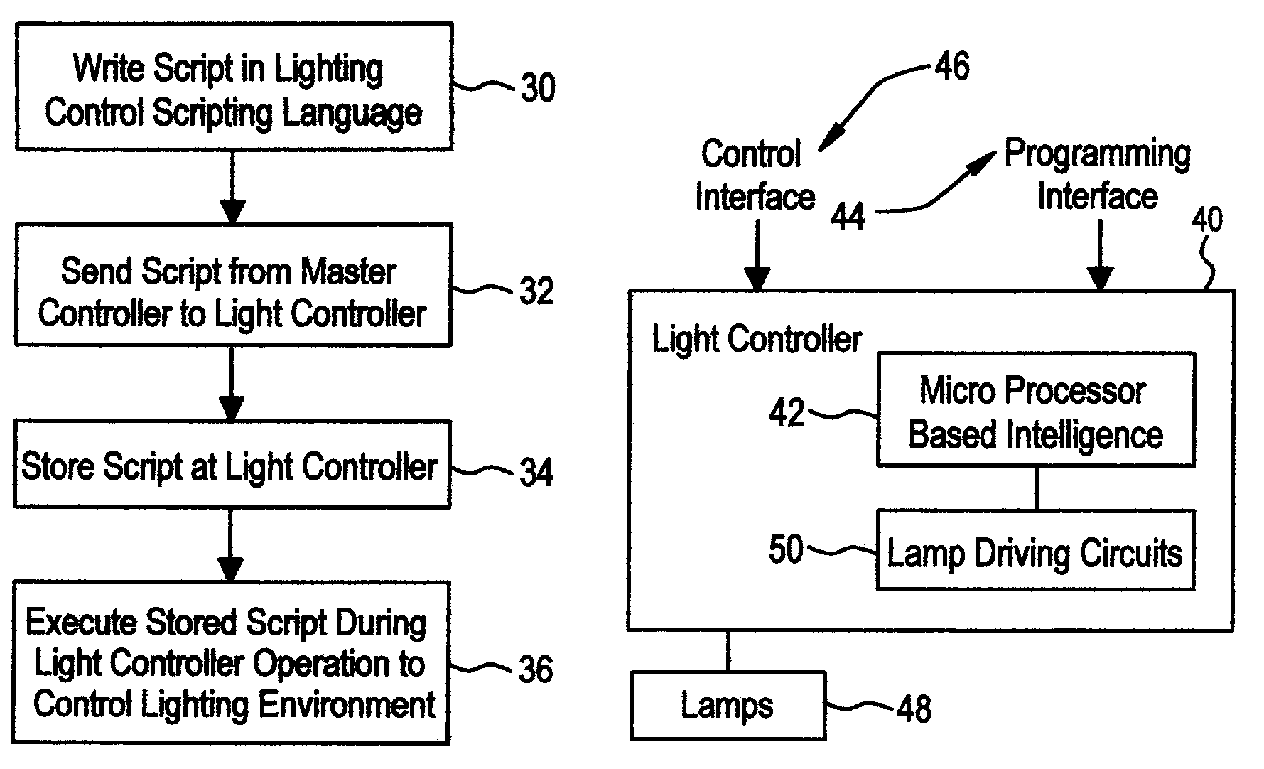
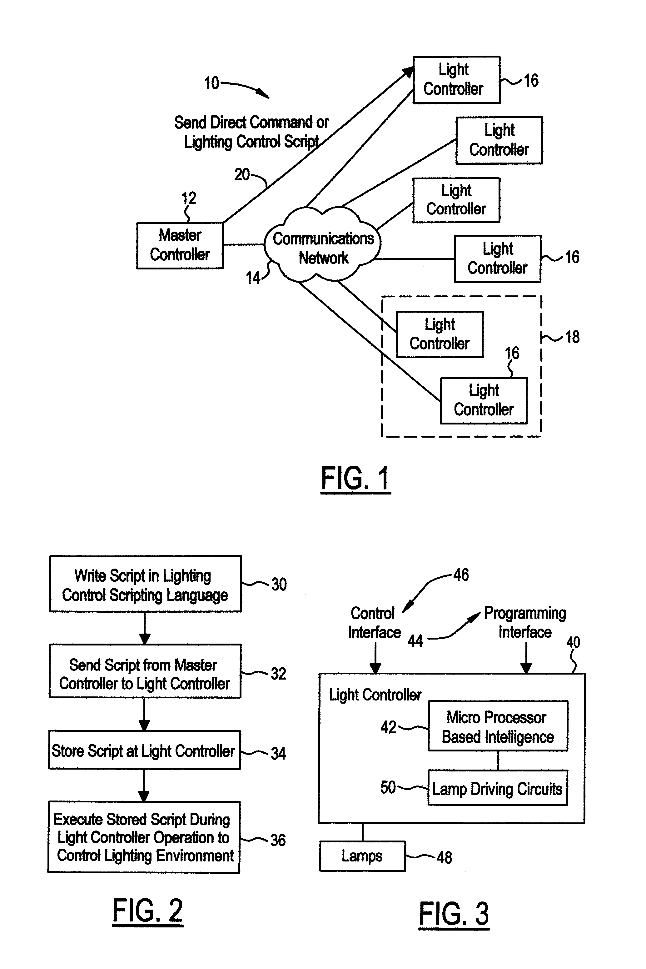
[0023]With reference to FIG. 1, a lighting system is generally indicated at 10. Lighting system 10 includes a master controller 12, a communications network 14, and a plurality of light controllers 16. As shown, several light controllers 16 may be grouped within a zone 18. Master controller 12 is operative to send a script to a light controller using communications network 14. Arrow 20 indicates master controller 12 sending a lighting control script to a light controller. In the alternative, master controller 12 may issue direct commands to light controllers. The light controller receiving the script stores the script in memory, and executes the stored script during operation. The lighting control script directs the control of the lighting.

[0024]Each light controller 16 includes a microprocessor-based intelligence that allows the device to independently store, calculate, and execute complex lighting scenarios without the necessity for any type of external control architecture. That ...


PUM


Abstract

A lighting control system includes a plurality of light controllers. Each light controller contains a microprocessor-based intelligence. The plurality of light controllers form a distributed architecture. The microprocessor-based intelligence is operative to store, calculate, and execute complex lighting scenarios. The microprocessor-based intelligence executes a lighting control script during operation. The lighting control script is sufficiently detailed and the light controller is sufficiently intelligent so as to allow the light controller to control lighting without the necessity of a having a present external control architecture.

Description

BACKGROUND OF THE INVENTION[0001]1. Field of the Invention[0002]The invention relates to lighting systems, programmable lighting controllers, and lighting fixtures including flourescent lamp ballasts and light emitting diode (LED) power sources.[0003]2. Background Art[0004]An existing lighting system includes a number of lighting fixtures and a controller in the form of a host computer. The host computer sends individual commands to each lighting fixture over a communication network. One problem in such a system is that a bottleneck in the communications may occur as lights are turned on and brightness is adjusted. Another problem in such a system is the failure of the system to operate when the host computer is disconnected.[0005]In another existing arrangement, programmable lighting circuit controllers have been used in certain applications where a wall-mounted controller controls a plurality of household lighting circuits. These controllers have limited capabilities, and have onl...

Claims


Application Information

Patent Timeline
Patent Type & Authority Patents(United States)
IPC IPC(8): H05B37/00
CPCH05B37/0254Y02B20/48H05B47/18Y02B20/40
Inventor SEARS, STORM S.MARTINELLI, JOHN
Owner BRUCE AEROSPACE
Why Eureka
Try Eureka