System and method for controlling ink concentration using a refractometer

a technology of refractometer and ink concentration, which is applied in the field of control of ink output, can solve the problems of affecting ink properties such as viscosity, system idle condition, and high evaporation rate of carrier fluid, and achieve the effect of accurate dye concentration measuremen

Inactive Publication Date: 2007-05-22
EASTMAN KODAK CO
View PDF20 Cites 45 Cited by
  • Summary
  • Abstract
  • Description
  • Claims
  • Application Information

AI Technical Summary

Problems solved by technology

As would be obvious to one skilled in the art, affecting ink properties such as viscosity is detrimental, since the energy required to stimulate filaments is determined partially by the viscosity of the fluid.
Alternatively, when little or no printing is being done, the system is in an idle condition and the evaporation rate of the carrier fluid is typically higher than the amount of ink removed during printing.
Small holes size errors or pressure variations can produce drop volumes larger or smaller than assumed by the control system.
Ink losses due to spillage or leakage can also not be accounted for.
As a result, this scheme can not maintain the ink concentration required for high print quality applications.
Furthermore, the resistivity of the ink also changes with time after the ink has been initially installed in the system.
As a result, resistivity is less than an ideal indicator of ink concentration.
Thus, these previous methods of concentration control are indirect and do not measure a property of the ink directly linked to concentration.
The small gap through which the fluid must pass in the optical cell can result in unacceptably high pressure drops at the required flow rates.
As a result, the '189 patent is not applicable for use with all inks.
This is not a practical option.

Method used


Image

  • System and method for controlling ink concentration using a refractometer
  • System and method for controlling ink concentration using a refractometer
  • System and method for controlling ink concentration using a refractometer

Examples


Embodiment Construction

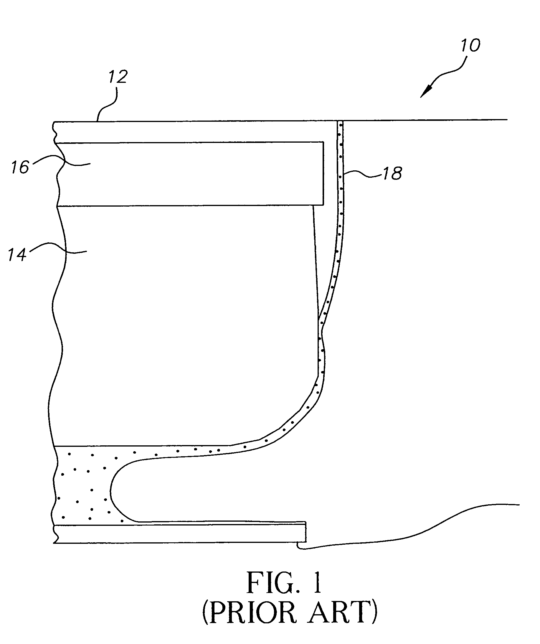
[0017]Referring now to the drawings, in FIG. 1, there is illustrated a prior art view of a drop generator and catcher assembly 10. A drop generator 12 is situated in an area above a catcher 14 and charge plate 16. The printhead defines one or more rows of orifices which receive an electrically conductive recording fluid from a pressurized fluid supply manifold and eject the fluid in rows of parallel streams. Printers using such printheads accomplish graphic reproduction by selectively charging and deflecting the drops in each of the streams and depositing at least some of the drops on a print receiving medium. The uncharged ink droplets flow along a trajectory path indicated by 18 in FIG. 1.

[0018]In continuous ink jet printer operation, printhead life is critical for optimum operation. Proper function of the printhead is dependent on ink properties such as viscosity, surface tension and concentration. These properties affect satellite-free drop formation, drop breakoff phase, catche...


PUM

PropertyMeasurementUnit
volumeaaaaaaaaaa
volumeaaaaaaaaaa
concentrationaaaaaaaaaa

Abstract

The present invention relates to ink output in ink jet printing systems. A refractometer is used to control the concentration of inks used in continuous ink jet printers. A concentration detector measures the total amount of light reflected from a surface. Changes in the ink cause a definite change in sensor output. As the refractive index is changed, shifting the critical angle for internal reflection, more or less light is reflected to the sensor. The index of refraction can be determined from the sensor once corrections are made to account for temperature dependencies of the sensor and light source and baseline measurement of reflected light amplitude. These dependencies are carried out in the refractometer.

Description

TECHNICAL FIELD[0001]The present invention relates to ink output in ink jet printing systems and, more particularly, to controlling the concentration of the ink output.BACKGROUND ART[0002]In a continuous ink jet fluid system, the ink used, which includes a carrier fluid, such as water or a solvent, and dye, is continuously recirculated through the system. As it is recirculated, it mixes with air in the return lines and is maintained under vacuum in the ink reservoir. Evaporation of the carrier fluid due to the air-ink interaction increases the dye concentration of the ink which changes various fluid properties such as viscosity and surface tension. Therefore the optimal parameters used to control the ink jet printing process change as the ink concentration varies. As would be obvious to one skilled in the art, affecting ink properties such as viscosity is detrimental, since the energy required to stimulate filaments is determined partially by the viscosity of the fluid.[0003]Proper ...

Claims


Application Information

Patent Timeline
Patent Type & Authority Patents(United States)
IPC IPC(8): G01N21/41
CPCG01N21/43G01N21/274G01N21/552G01N2021/1774G01N2021/414G01N2201/062
Inventor MCCANN, JAMES D.DEVIVO, DANIEL J.TRAPP, JEFFREY S.
Owner EASTMAN KODAK CO
Why Eureka
Try Eureka