Scanning device and method of scanning an optical beam over a surface

a scanning device and optical beam technology, applied in the field of scanning devices and methods of scanning optical beams over a surface, can solve the problems of galvanometer scanners with limited accuracy, mirrors that are not large enough for the optical system, and more of a problem

Inactive Publication Date: 2007-05-22
CLVR
View PDF6 Cites 3 Cited by
  • Summary
  • Abstract
  • Description
  • Claims
  • Application Information

AI Technical Summary

Problems solved by technology

Although galvanometer scanners have been very successful in scanning lasers for reshaping corneal tissue and a large range of other applications, they do have some disadvantages.
Sometimes this results in mirrors that are not large enough for the optical system or using mirrors that are too thin to maintain their required flatness during the scanning process.
Galvanometer scanners also have limited accuracy when the desired scan angle is small (less than 3 degrees).
This becomes even more of a problem when the demands of customised surgery require smaller spot sizes to ablate with higher precision and subsequently much higher pulse repetition rates.
Galvanometric scanners would not have adequate response for such a laser system.
A problem that sometimes occurs in galvanometric scanners if the eye moves slightly up and down, getting closer or further away from the laser, is that each pulse may not hit the eye in the correct position.
However, piezoelectric drives also have a number of significant disadvantages, and although they have been used to scan laser beams, they have not been generally accepted for this type of application because of these disadvantages.
The main disadvantage of piezoelectric drive systems is their very limited range of movement.
They are therefore not considered to be a potential means of scanning in applications currently performed by galvanometer scanners.
However, this type of technique creates a non-linear beam deflection and loses much of the potential accuracy of a piezoelectric drive mechanism, and still has a much smaller range of scanning than galvanometer scanners.
These types of techniques also suffer from reduced response time, stiffness and have a significantly smaller force / load capability.
The second significant problem with piezoelectric drive systems, or actuators, is that they have significant hysteresis.
This hysteresis is another key reason why piezoelectric driven scanners are currently not used in applications requiring fast complex scan pattens, such as laser systems for refractive surgery.
The problem with this is that it significantly reduces the response of the system, and its accuracy is reduced to the accuracy of the sensor.
In an application in which tolerances are critical, such as refractive surgery, the hysteresis induced error can be so large that the piezoelectric signal and position sensor signal cannot be compared to check the system is operating correctly.
However, this description complains of the lack of range of such a scanning mechanism as special effort is required to scan the laser across the entrance of a single optical fibre.
Acousto-optic scanners are relatively complex, have high optical losses and are not suitable for many of the wavelengths used for material processing applications.

Method used


Image

  • Scanning device and method of scanning an optical beam over a surface
  • Scanning device and method of scanning an optical beam over a surface
  • Scanning device and method of scanning an optical beam over a surface

Examples


Embodiment Construction

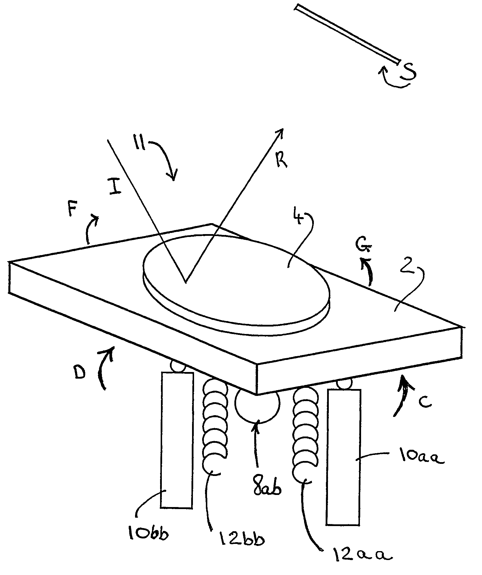
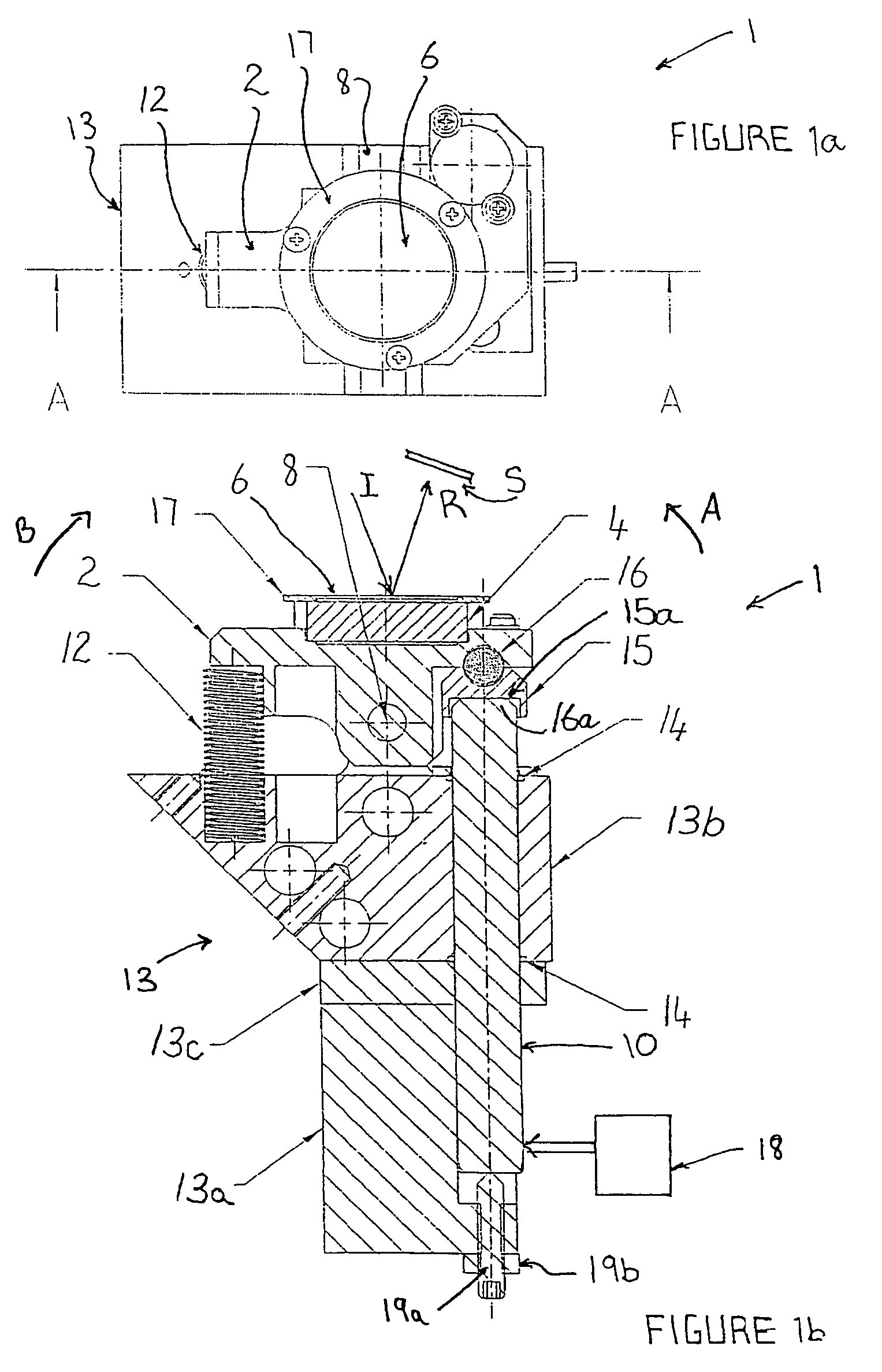
[0103]In FIGS. 1a and 1b, there is shown an optical scanning device 1 that is able to reflect an incident optical beam I so that the reflected optical beam R can be directed to a surface S such that the reflected optical beam R is scanned over the surface S.

[0104]The optical scanning device 1 comprises a platform 2, a mirror 4 having a reflective surface 6, a pivot 8 about which the platform 2 is able to pivot, a piezoelectric stack actuator 10 to pivot the platform 2 about the pivot 8 in a first direction, and a resilient spring 12 to bias the platform 2 about the pivot 8 in a second direction that is opposed to the first direction. The pivot 8 is a pivot shaft.

[0105]The optical scanning device 1 is further provided with a body 13 to support the other components of the optical scanning device 1. The body 13 comprises an anchor block 13a and a main block 13b that are separated by a spacer 13c. The main block 13b supports the piezoelectric stack actuator 10. A pair of O rings 14 are ...


PUM

PropertyMeasurementUnit
lengthaaaaaaaaaa
scan angleaaaaaaaaaa
distanceaaaaaaaaaa

Abstract

An optical scanning device (1) to scan an optical beam over a surface (S). The optical scanning device (1) uses a piezoelectric actuator (10) acting on a platform (2) that carries a mirror (4) to pivot the platform (2) about a pivot (8). Voltage is applied to the piezoelectric actuator (10) to pivot the platform (2) about the pivot (8). Changes in the applied voltage result in the angle at which the beam is reflected by the mirror (4) being altered. In this way, the reflected beam (R) can be scanned to different locations on the surface (S). Providing two such optical scanning devices (1a, 1b) or using two piezoelectric actuators (10aa, 10bb) acting on a single platform (2) enables two dimensional scanning of the surface (S) by the optical scanning device / s (1,1a, 1b). The optical scanning device (1) of the present invention may be used in refractive eye surgery laser apparatus.

Description

FIELD OF THE INVENTION[0001]The present invention relates to an optical scanning device, a laser apparatus incorporating such an optical scanning device and a method of scanning an optical beam over a surface to perform material processing of the surface.[0002]The applications of the present invention include, for example, surgical and medical applications, such as operations for correcting refractive errors of the eye by photorefractive keratectomy (PRK) or laser in-situ keratomileusis (LASIK). The present invention also has industrial applications for material processing. Material processing examples of industrial applications of the present invention include photolithography in microchip manufacture and glass marking.BACKGROUND OF THE INVENTION[0003]The specification refers to and describes content of U.S. Pat. Nos. 5,520,679, 6,339,278, 6,339,470 and 6,342,751. However, neither the disclosures in those US patents nor the description contained herein of content of those US patent...

Claims


Application Information

Patent Timeline
Patent Type & Authority Patents(United States)
IPC IPC(8): G02B26/08A61B18/20A61F9/01B23K26/08B23K26/082G02B26/10
CPCA61F9/008B23K26/08B23K26/0807G02B26/101A61B2018/2095A61F2009/00872B23K26/082A61B2018/20359
Inventor VAN SAARLOOS, PAUL PHILLIP
Owner CLVR
Why Eureka
Try Eureka