
Foreground detection

a detection field and foreground technology, applied in the field of foreground detection, can solve the problems of large number of cameras, high cost of purchasing or leasing such a system, and high cost of deploying a system, so as to reduce errors and reduce tim

Active Publication Date: 2007-05-22
SPORTSMEDIA TECH CORP
View PDF10 Cites 29 Cited by
  • Summary
  • Abstract
  • Description
  • Claims
  • Application Information

AI Technical Summary

Benefits of technology

[0010]The present invention, roughly described, pertains to technology for finding the foreground in still images or video images. Finding the foreground can be used to reduce errors and reduce the time needed when creating morphs of an image. Creating morphs using the foreground detection technology of the present invention can be used to create virtual camera movement with significantly less cameras than the prior art described above.

Problems solved by technology

One shortcoming of the system disclosed in the '323 patent is that it requires a large number of cameras.
Such a system is very expensive to deploy.
The cost of purchasing or leasing such a system will be very expensive.
The cost of maintaining, transporting and setting up the equipment will be too expensive for such a system to be used on a regular basis.
Additionally, many events take place simultaneously or close in time at different locations; therefore, many systems would be needed, which further drives up the costs.
A system that uses a large amount of camera may also be impractical from a logistics point of view.
For example, a system that uses thirty cameras may not be able to be deployed at all stadiums or theaters because of a lack of space to place the cameras.

Method used


Image

  • Foreground detection
  • Foreground detection
  • Foreground detection

Examples


Embodiment Construction

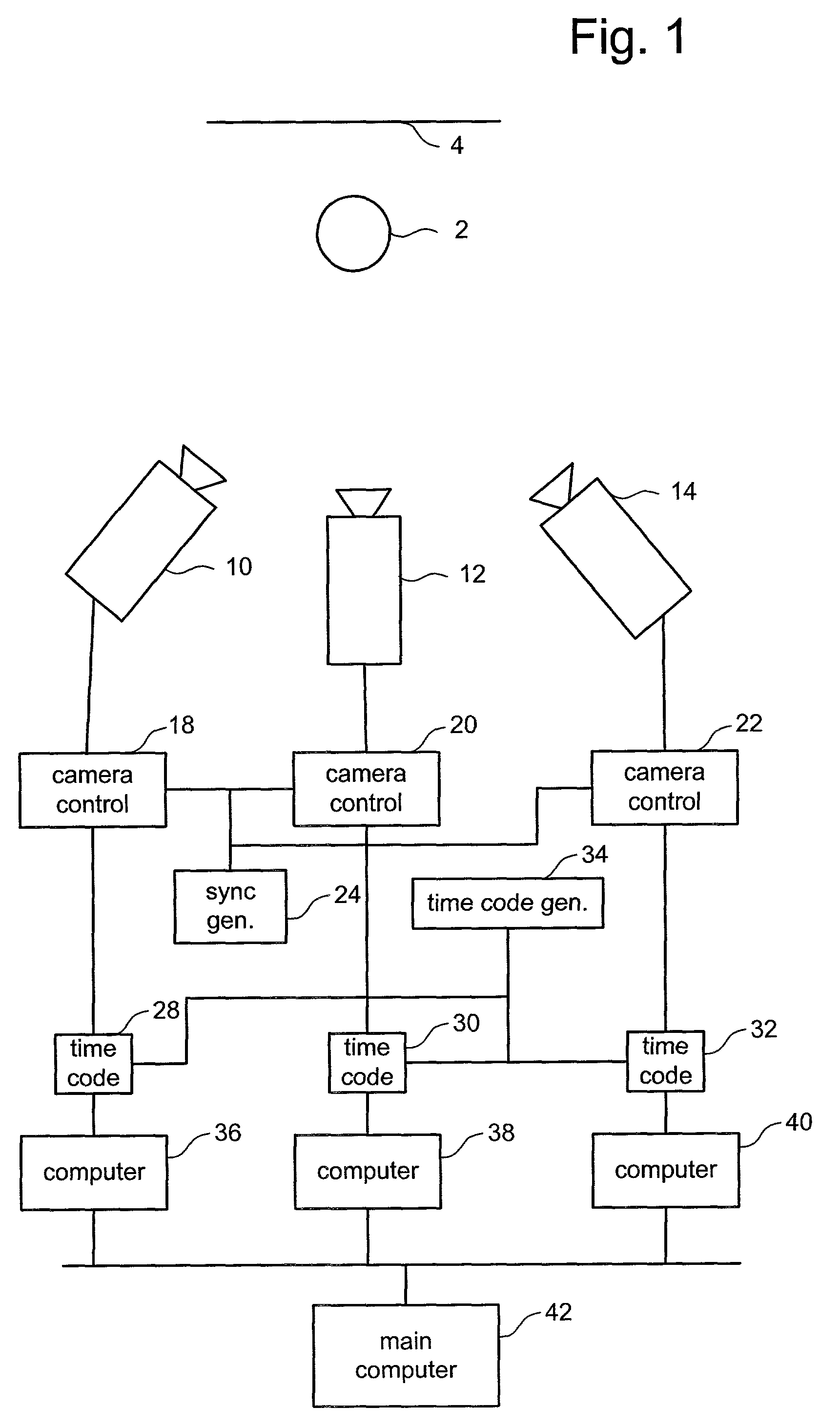
[0027]FIG. 1 is a block diagram depicting the components of one embodiment of the present invention. At the top of FIG. 1 is a scene being captured by a set of cameras. The scene includes a set of one or more foreground objects 2 and a set of one or more background objects 4. The scene is being captured by video cameras 10, 12 and 14. Although FIG. 1 depicts video cameras, the present invention also works with still cameras and other suitable sensors (e.g., infrared sensors, etc.). Connected to the cameras are camera control electronics 18, 20 and 22. Camera control electronics 18 is connected to camera 10. Camera control electronics 20 is connected to camera 12. Camera control electronics 22 is connected to camera 14. In one embodiment, cameras 10, 12 and 14 are Sony DXC-390 cameras and are spaced 10 degrees apart. In other embodiments, the cameras can be spaced further apart or less further apart. Note that while FIG. 1 shows three cameras, the present invention works with more or...


PUM


Abstract

A system is disclosed that can find an image of a foreground object in a still image or video image. Finding the image of the foreground object can be used to reduce errors and reduce the time needed when creating morphs of an image. One implementation uses the detection of the image of the foreground object to create virtual camera movement, which is the illusion that a camera is moving around a scene that is frozen in time.

Description

[0001]This application claims the benefit of U.S. Provisional Application No. 60 / 256,420, Foreground / Background Detection, filed Dec. 18, 2000, incorporated herein by reference.BACKGROUND OF THE INVENTION[0002]1. Field of the Invention[0003]The present invention is directed to technology for finding the foreground of an image.[0004]2. Description of the Related Art[0005]Virtual camera movement has become an increasingly popular effect for instant reply during sporting events, commercials, movies and other video applications. Virtual camera movement conveys the illusion that a camera is moving around a scene frozen in time. In most cases, the scene is depicted in a three dimensional manner. For example, virtual camera motion has been used in the movie “The Matrix,” and in commercials for the Gap, AT&T and Discover.[0006]One example of virtual camera movement can be found in U.S. Pat. No. 5,659,323, “System for Producing Time-Independent Virtual Camera Movement in Motion Pictures and ...

Claims


Application Information

Patent Timeline
IPC IPC(8): G06K9/34
CPCG06T7/0081G06T7/0097G06T15/205H04N5/2627G06T2207/10016G06T2207/20144G06T7/11G06T7/174G06T7/194
Inventor GLOUDEMANS, II, JAMES R.HSIAO, WALTER
Owner SPORTSMEDIA TECH CORP
Learn More