Driving device and measuring instrument

a driving device and measuring instrument technology, applied in the direction of instruments, mechanical measuring arrangements, manufacturing tools, etc., can solve the problems of denting and curved central part of the measuring table, reducing so as to improve the accuracy of detecting the accuracy of the scale member, improve the rigidity of the base table, and improve the effect of accuracy

Active Publication Date: 2007-05-29
MITUTOYO CORP
View PDF21 Cites 25 Cited by
  • Summary
  • Abstract
  • Description
  • Claims
  • Application Information

AI Technical Summary

Benefits of technology

[0026]Herein, a component subject to deformation may be only either one of the base table or the guide rail, and may be both the base table and the guide rail. When both the base table and the guide rail are deformed, each deformation is accepted in the holding section, so that a form of each of the base table and the guide rail can be maintained without affecting each other.
[0071]In the present invention, deformation of the base table (measuring table) does not affect the guide rail, it is contemplated that there is no problem in a slight deformation of the base table owing to weight of a workpiece or the like, which eliminates the need for enhancing rigidity of the base table, so that it is possible to reduce the thickness of the base table.

Problems solved by technology

There occurs a problem, however, that, because the guide rail 41 is integrated with the measuring table 3, the guide rail 41 and the measuring table 3 cannot maintain each form independently to each other, so that, when one is deformed, the other is correspondingly deformed.
For instance, when a workpiece W is put on the table surface 31, as shown in FIG. 9A, there is a disadvantageous possibility that the central part of the measuring table 3 is dented and become curved owing to weight of the workpiece W. The result is that the guide rail 41 also becomes curved.
When the guide rail 41 is deformed as described above, there occurs a problem that the beam supporting body 42 is not guided straight and is deviated from a proper track.
As a result, an error is generated in the position of the stylus 2, so that there occurs a problem that measuring accuracy is deteriorated.
Further, when the guide rail 41 becomes curved, harmful loading imposed on the driving mechanism 4 is increased, which degrades a driving performance of the driving mechanism 4.
As a result, control characteristics change, which increases unnecessary harmful vibration.
Further, when harmful loading imposed on the driving mechanism 4 is increased, a portion thereof subject to sliding is intensively abraded.
Then an economic loss such as deterioration in a life cycle thereof as a product, an increase in cost of maintenance or the like is caused.
Further, when the guide rail 41 becomes curved, the scale member is also curved, so that there occurs a problem that measuring accuracy of the driving sensor is deteriorated.
Degraded measuring accuracy of a stylus coordinate not only leads to an error in measuring, but also generates an error in positioning of the stylus 2.
With the problems described above occurred when the guide rail 41 becomes curved, it has been difficult to improve the driving performance (including track accuracy, driving speed and positioning accuracy) and also to improve detecting accuracy of the driving sensor.

Method used


Image

  • Driving device and measuring instrument
  • Driving device and measuring instrument
  • Driving device and measuring instrument

Examples


Embodiment Construction

)

[0081]An embodiment of the present invention is shown below with reference to the related drawings, and is also described with reference to the reference numerals designated to each component in the drawings.

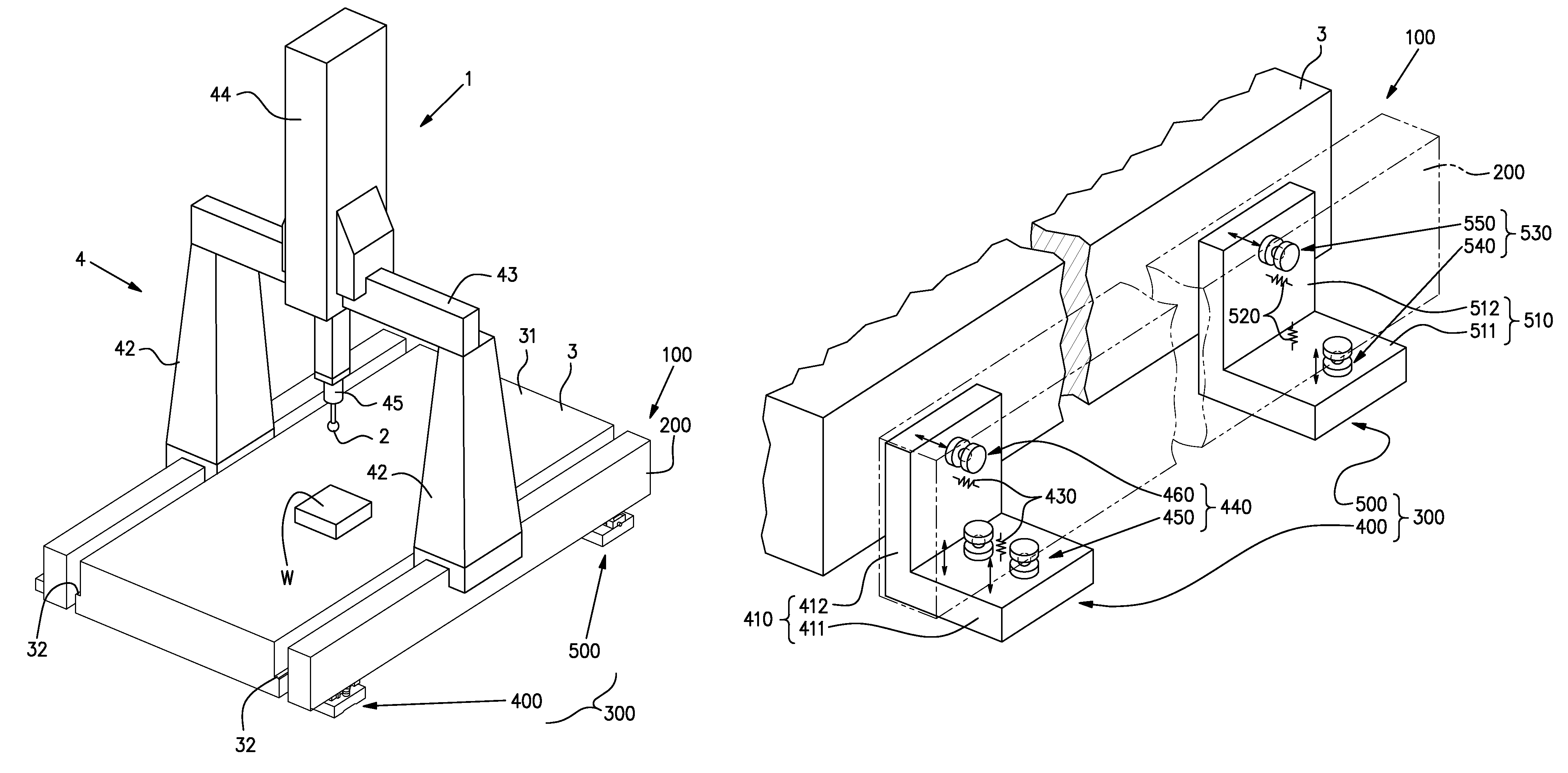
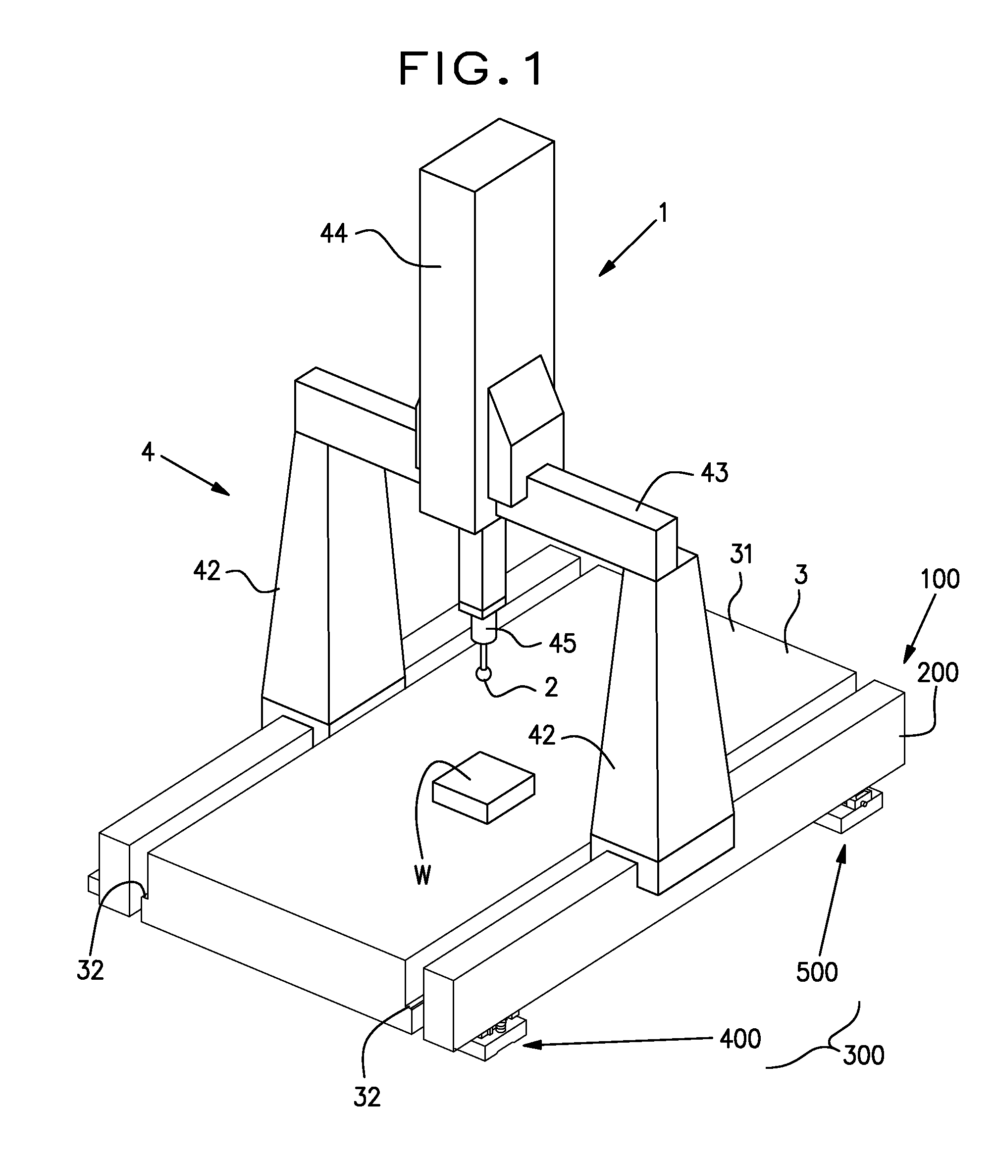
[0082]A general perspective illustration of an embodiment concerning a guide rail device according to the present invention is shown in FIG. 1. In FIG. 1, a guide rail device 100 is mounted on each of both side faces of a measuring table (base table) 3.

[0083]The measuring table 3 is substantially the same as that explained in the description of related art, and has a table surface 31 formed to be substantially flat. Each of both side faces of the measuring table 3 is provided with a flange mounting section 32 formed to be projected in a flange-like form.

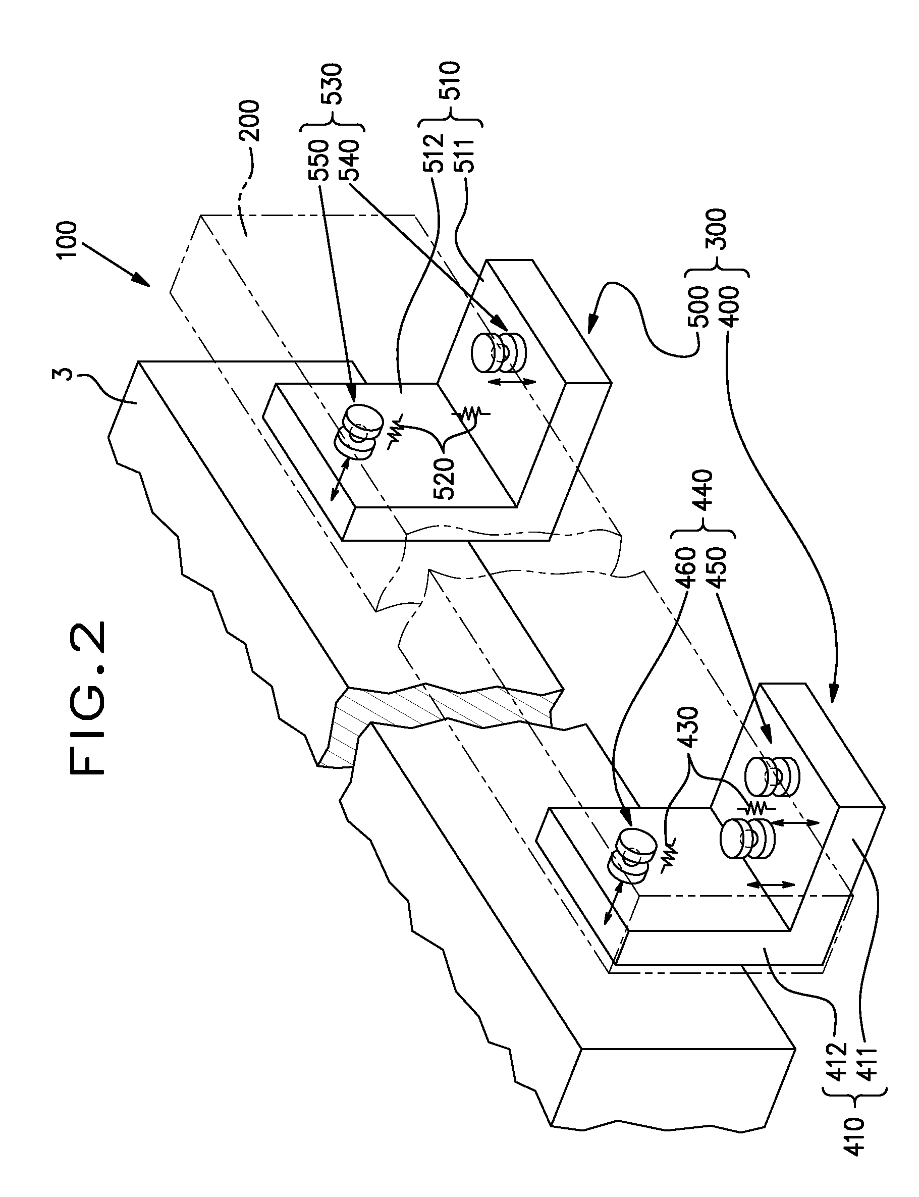
[0084]The guide rail device 100 comprises a guide rail 200 formed straight in the longitudinal direction thereof, a supporting device 300 supporting the guide rail 200 on a side face of the measuring table 3.

[0085]The guide rail...


PUM


Abstract

A supporting device (300) for supporting a guide rail (200) for guiding a movable member subjected to relative displacement in relation to the base table (3). The supporting device includes, base bodies (410, 510) engaged onto the base table (3) and carrying the guide rail (200), and holding section (440, 530) for holding the guide rail (200) intervening between the guide rail (200) in the state where the guide rail is carried by the base bodies (410, 510). The holding section (440, 530) supports the guide rail (200) in the state where it can move swingingly. A change in the posture or position of the base bodies (410, 510) is offset with a swinging movement by the holding section, and does not affect the guide rail. As a result, excessive force is not applied on the guide rail, so that the form of the guide rail is maintained.

Description

BACKGROUND OF THE INVENTION [0001]1. Field of the Invention[0002]The present invention relates to a guide rail supporting device, a guide rail device, a driving device and a measuring instrument.[0003]2. Description of Related Art[0004]There has been known a driving device having a guide rail as a guide mechanism, and there has also been known a measuring instrument with which a stylus is three-dimensionally displaced by this driving device to measure a form of a workpiece (refer to, for instance, Japanese Patent Publication No. HEI 3-45321).[0005]In FIG. 8 is shown a coordinate measuring instrument 1 as an example of the measuring instrument.[0006]The coordinate measuring instrument 1 comprises a stylus 2 applied onto a workpiece W for detecting a surface of the workpiece, a measuring table 3 having a table surface 31 for pulling thereon the workpiece W, a driving mechanism (driving device) 4 directly provided on the measuring table 3 for three-dimensionally moving the stylus 2, an...

Claims


Application Information

Patent Timeline
Patent Type & Authority Patents(United States)
IPC IPC(8): G01B5/004G01B21/00B23Q1/26G01B5/00
CPCF16C29/001G01B5/0009G01B5/0014
Inventor KIKUCHI, SHIGEO
Owner MITUTOYO CORP
Why Eureka
Try Eureka