Cover for a concrete construction

Active Publication Date: 2007-05-29
DAYTON SUPERIOR CORP
View PDF37 Cites 60 Cited by
  • Summary
  • Abstract
  • Description
  • Claims
  • Application Information

AI Technical Summary

Benefits of technology

[0009]In another exemplary embodiment, the height of the fins on each anchor-engaging member, as measured from the sides of the anchor-engaging members, decreases with the distance that the fins are located from the distal end of the anchor-engaging members. The fins are formed from a material which permits them to deform and thereby frictionally hold the cover in place when the anchor-en

Problems solved by technology

However, the cover of Holt et al. contains multiple pieces which may become separated at the job site, resulting in an unusable cover.
Because it may be difficult to maneuver the plug into the hol

Method used


Image

  • Cover for a concrete construction
  • Cover for a concrete construction
  • Cover for a concrete construction

Examples


Embodiment Construction

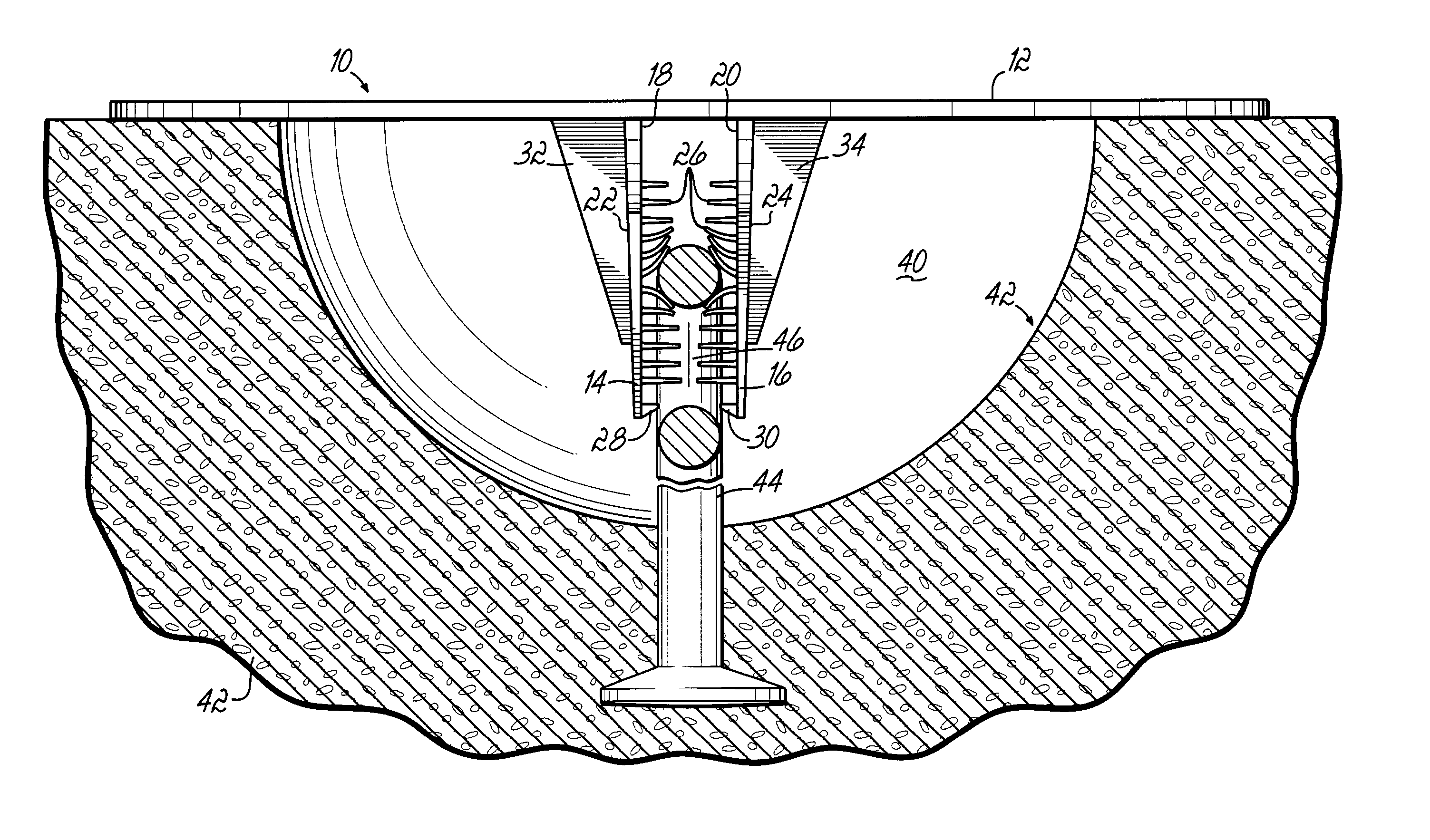
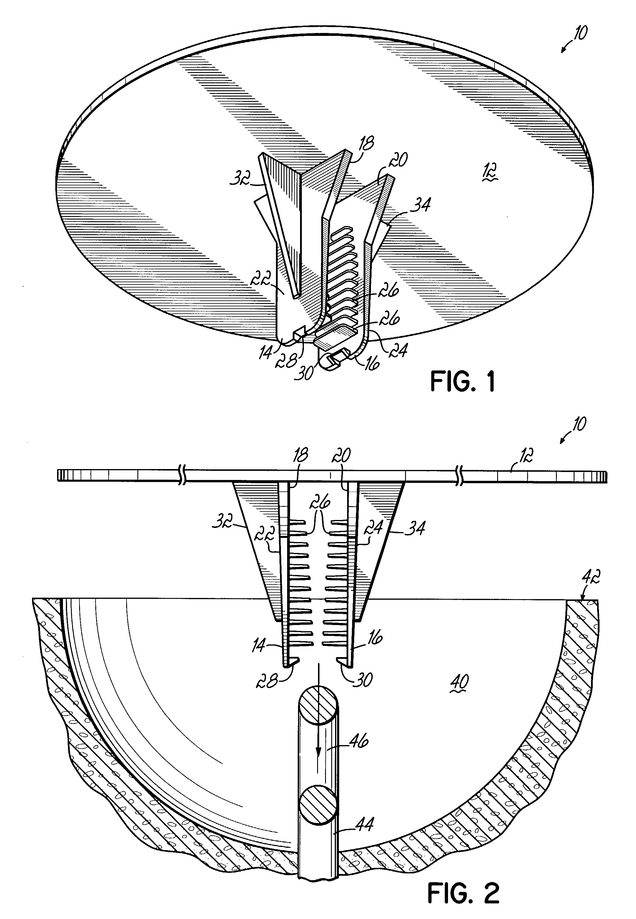
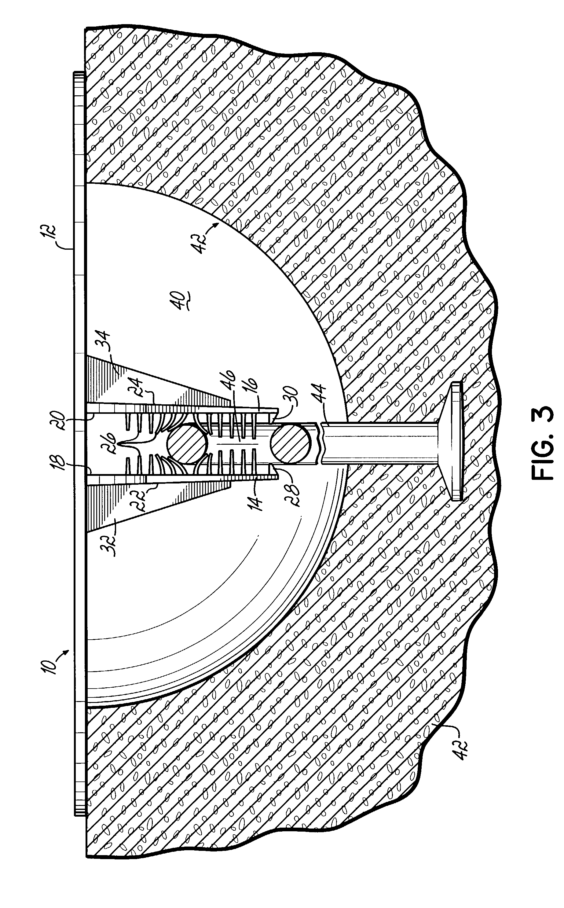
[0017]Referring to FIGS. 1–3, there is shown an exemplary cover 10 for a concrete construction. The cover 10 includes a generally disk-shaped body member 12 which is sized to completely cover a recess 40 which has been formed into a concrete construction 42 to surround an anchor 44 embedded into the concrete 42. First and second anchor-engaging members 14,16 are located near the central portion of the body member 12 and extend away from the body member 12. The anchor-engaging members 14, 16 are spaced apart a distance to permit the anchor 44 of the concrete construction 42 to be received between opposing first sides 18, 20 of the first and second anchor-engaging members 14, 16.

[0018]A plurality of fins 26 are arranged on the first sides 18, 20 of the first and second anchor-engaging members 14, 16. The fins 26 are arranged on each anchor-engaging member 14, 16 in a generally parallel arrangement and extend from the first sides 18, 20 of the anchor-engaging members 14, 16 toward the ...


PUM


Abstract

A cover for a concrete construction has a pair of anchor-engaging members extending from a disk-shaped body. The anchor-engaging members include fins which are configured to engage an anchor formed into a recess of a concrete block or wall to cover the recess. The cover is easily installed to the anchor by positioning the cover over the recess and urging the anchor-engaging member into engagement with the anchor.

Description

FIELD OF THE INVENTION[0001]The present invention pertains to concrete building materials, and more particularly to a cover which may be used to close off a recess formed in a concrete section, such as a wall panel or other concrete structure.BACKGROUND OF THE INVENTION[0002]Concrete is often used as a building material in the construction of commercial buildings and other structures. Typically, concrete will be formed into blocks or panels which may thereafter be assembled at a job site into a desired structure. The blocks and panels may be formed at a manufacturing plant for transportation to the job site, or they may be formed directly at the job site. For example, concrete panels which are used to construct concrete walls are generally formed by pouring concrete into forms which have been arranged on a horizontal surface, such as the floor of a building under construction. Once a concrete panel has sufficiently cured, the panel may be raised into position to form a wall section....

Claims


Application Information

Patent Timeline
IPC IPC(8): E04B1/34E04G15/04E04G21/14E04G23/02
CPCE04G15/04E04G21/142E04G23/0203
Inventor FRANCIES, III, SIDNEY E.HALLAM, MARK S.LANCELOT, III, HARRY B.
Owner DAYTON SUPERIOR CORP
Why Eureka
Try Eureka