Hydraulic system with multiple pressure relief levels

a technology of pressure relief and hydraulic system, applied in the direction of fluid couplings, servomotors, couplings, etc., can solve the problems of relatively high control cost and rendered the third valve section inoperabl

Inactive Publication Date: 2007-05-29
HUSCO INT INC
View PDF6 Cites 31 Cited by
  • Summary
  • Abstract
  • Description
  • Claims
  • Application Information

AI Technical Summary

Benefits of technology

[0017]The primary pressure relief valve ensures that the pressure in the hydraulic system never exceeds the first pressure limit and the second pressure relief v

Problems solved by technology

However, each of those functions has a unique pressure characteristic which dictates that its maximum pressure be limited to a different magnitude.
This type of control was relatively expensive as a pressure relief valve was requir

Method used


Image

  • Hydraulic system with multiple pressure relief levels
  • Hydraulic system with multiple pressure relief levels
  • Hydraulic system with multiple pressure relief levels

Examples


Embodiment Construction

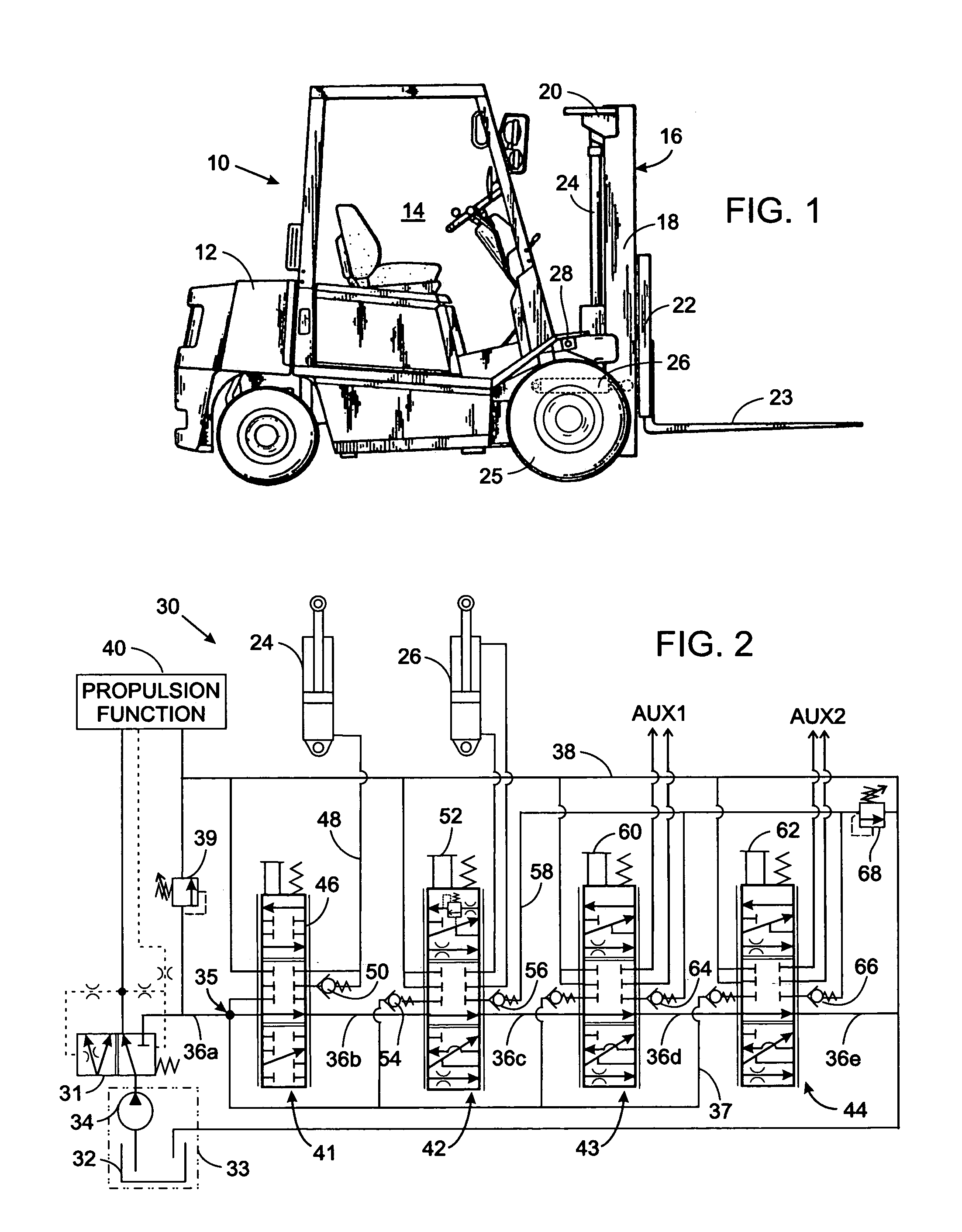
[0021]The present invention will be described in the context of a hydraulic system for a lift truck, such as the one shown in FIG. 1, with the understanding that the inventive concepts can be applied to hydraulic systems for a wide variety of other types of equipment and machines.

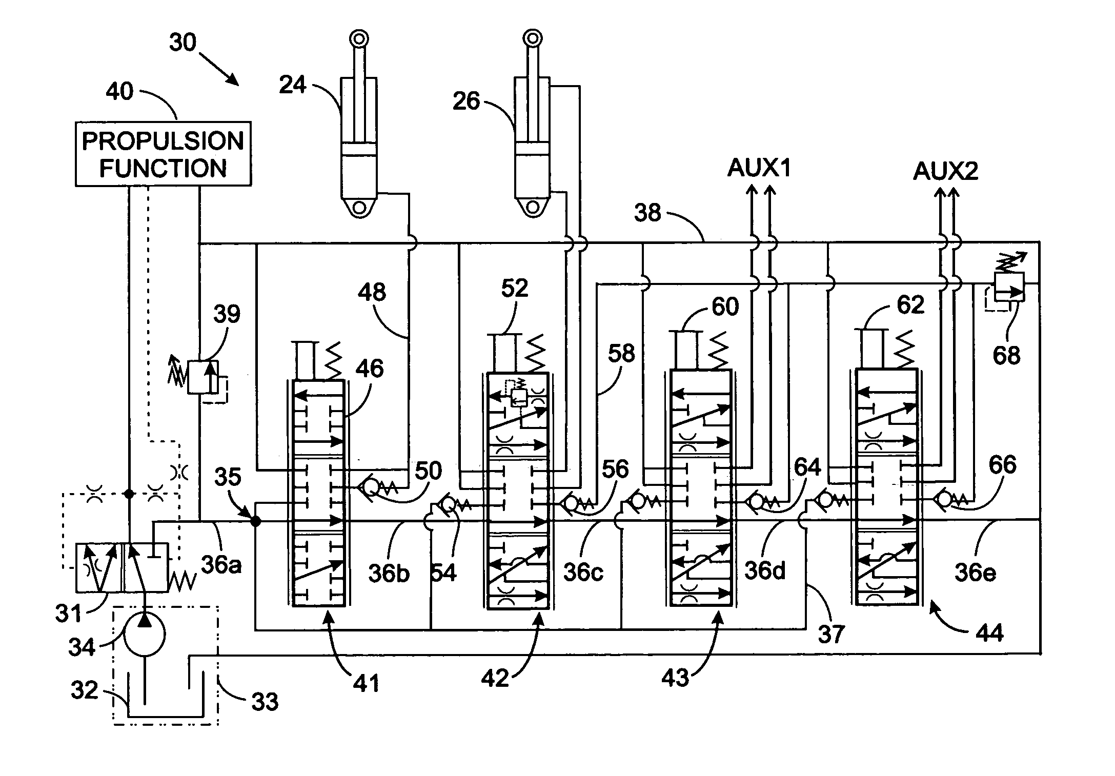
[0022]With reference to FIG. 2, the hydraulic system 30 for the lift truck 10 has a source 33 of hydraulic fluid which includes a reservoir 32 from which hydraulic fluid is drawn by a pump 34 and forced under pressure to a pressure control valve 31. The pressure control valve 31 responds to the hydraulic fluid pressure demands of the propulsion function 40 that drives the wheels 25 of the lift truck 10. Typically the vehicle propulsion tales priority over other hydraulic functions, and the pressure control valve ensures that those pressure demands are met to propel the lift truck. Thus the pressure control valve 76 directs the pump output fluid to the propulsion function 40 and any of that output fluid rema...


PUM


Abstract

A hydraulic system has at least one primary hydraulic functions and a plurality of secondary hydraulic functions all of which are connected in parallel to a supply conduit and a return conduit. A first pressure relief valve prevents pressure in the supply conduit from exceeding a first limit and second pressure relief valve prevents the pressure at the secondary hydraulic functions from exceeding the lower second pressure limit. Novel pressure relief circuits are provided which enable only two pressure relief valves to provide one of two pressure limits at more than two hydraulic functions.

Description

CROSS-REFERENCE TO RELATED APPLICATIONS[0001]Not ApplicableSTATEMENT REGARDING FEDERALLY SPONSORED RESEARCH OR DEVELOPMENT[0002]Not ApplicableBACKGROUND OF THE INVENTION[0003]1. Field of the Invention[0004]The present invention relates to hydraulic systems that independently control the operation of a plurality of hydraulic actuators, and more particularly to such hydraulic systems in which various hydraulic actuators have different operating pressure limits as determined by separate pressure relief valves.[0005]2. Description of the Related Art[0006]Numerous types of machines have components that are moved by a hydraulic system. For example, a lift truck is vehicle for transporting objects throughout a factory or warehouse and has an engine which drives a pump to provide pressurized fluid for powering different functions, such as driving wheels to propel the vehicle or lifting the objects.[0007]An exemplary lift truck 10 is shown in FIG. 1 and includes a body 12 with an operator co...

Claims


Application Information

Patent Timeline
IPC IPC(8): F15B11/16F15B11/00
CPCB66F9/22F15B11/165F15B21/08F15B2211/3116F15B2211/40523F15B2211/45F15B2211/50518F15B2211/6054F15B2211/6346F15B2211/654
Inventor DORNBACH, DAVID A.
Owner HUSCO INT INC
Why Eureka
Try Eureka