Semiconductor device package with reduced leakage

a technology of semiconductor devices and encapsulants, which is applied in the direction of semiconductor devices, semiconductor/solid-state device details, electrical equipment, etc., can solve the problems of encapsulant leakage at the plastic, degradation of the interface between the different parts of the package, and the non-hermetic plastic package fabricated in this or similar fashion

Active Publication Date: 2007-05-29
BELL SEMICON LLC
View PDF22 Cites 66 Cited by
  • Summary
  • Abstract
  • Description
  • Claims
  • Application Information

AI Technical Summary

Benefits of technology

[0009]In accordance with one aspect of our invention, a semiconductor device package comprises a container including a base and sidewalls of materials having different thermal expansion coefficients. The base is configured to support a semiconductor device chip, and a lead frame extends through at least one of the sidewalls. The package is characterized in that a portion of the lead frame within the sidewall has at least one aperture penetrating into the lead frame. The sidewall material extends into (e.g., molds around) the aperture, thereby forming a strong interfacial bond that provides a low leakage, sidewall-lead-frame interface.
[0010]In accordance with another aspect of our invention, the base has a reentrant feature that is positioned within the thickness of at least one of the sidewalls. This feature acts to engage or capture the side wall in such a way as to provide a strong, low leakage base-sidewall interface.
[0011]In accordance with yet another aspect of our invention, the top surface of the base has a groove that is positioned within the thickness of at least one of the sidewalls and engages the at least one sidewall, thereby forming a low leakage base-sidewall interface.

Problems solved by technology

We have found that non-hermetic plastic packages fabricated in this or similar fashion have a number of problems associated with encapsulant leaking out of the cavity during the cavity fill process.
However, after die attach and wire bonding, when the packages are typically filled with encapsulant, we have observed that encapsulant does leak out at the plastic-to-metal interfaces of the package.
This leakage results primarily from degradation of the interfaces between the different parts of the package, which in turn results from differences in the thermal expansion coefficients of the base, lead frame and sidewall materials as well as from less than ideal design.
In addition, these leaky interfaces also permit harmful substances (e.g., moisture, solvents, air-born particles) from the ambient to enter the package, where they can have a deleterious effect on device operation or package integrity.

Method used


Image

  • Semiconductor device package with reduced leakage
  • Semiconductor device package with reduced leakage
  • Semiconductor device package with reduced leakage

Examples


example

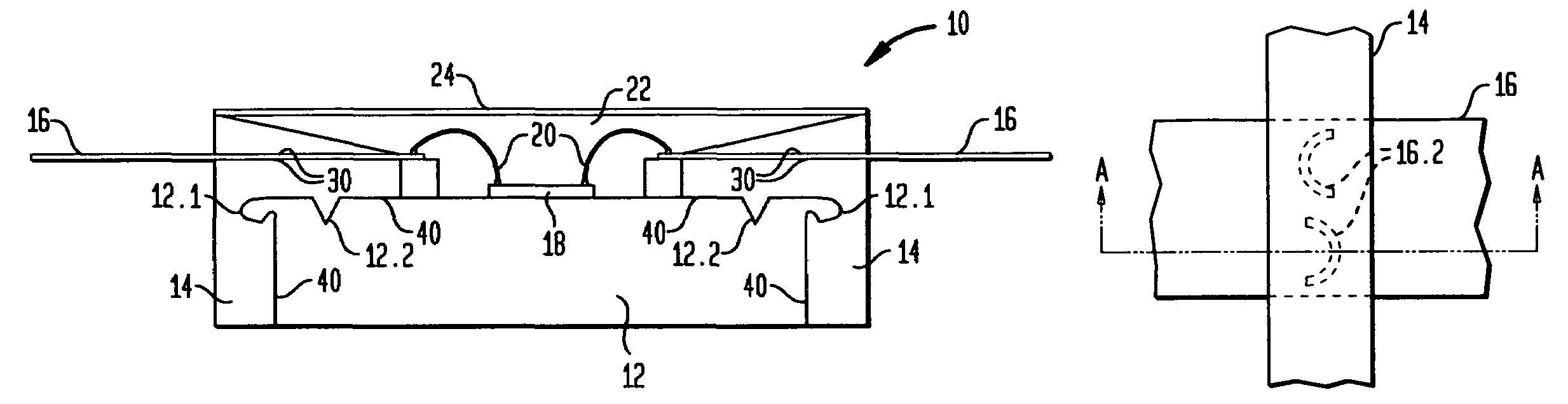
[0031]This example describes the fabrication of a package for RFLDMOS (i.e., radio frequency, laterally diffused, metal-oxide-semiconductor) ICs, in accordance with one embodiment of our invention. Various materials, dimensions and operating conditions are provided by way of illustration only and, unless otherwise expressly stated, are not intended to limit the scope of the invention. This type of package illustratively contains six chips: two chips that function as active ICs (i.e., high power RFLDMOS transistors) and four that function as passive ICs (i.e., capacitors).

[0032]The container 12 had overall dimensions of 810 mils in length, 385 mils in width, and 99 mils in height. The sidewalls 14 and lid 24 were made of a liquid crystal polymer (LCP) material (e.g., Ticona Vectra S-135). The sidewalls were 72.5 mils thick in the region where the lead frame extended through the sidewalls, whereas the lid 24 had overall dimensions of 810 mils in length, 384 mils in width, and 43 mils ...


PUM


Abstract

A semiconductor device package comprises a container including a base and sidewalls. The base is configured to support a semiconductor device chip, and a lead frame extends through at least one of the sidewalls. A portion of the lead frame within the sidewall has at least one aperture penetrating into the lead frame. The sidewall material extends into the aperture, thereby forming a strong interfacial bond that provides a low leakage, sidewall-lead-frame interface. The base has a reentrant feature that is positioned within the thickness of at least one of the sidewalls and engages the at least one sidewall, thereby forming a low leakage base-sidewalls interface. The top surface of the base has a groove that is positioned within the thickness of at least one of the sidewalls and engages the at least one sidewall, thereby enhancing the low leakage base-sidewall interface.

Description

BACKGROUND OF THE INVENTION[0001]1. Field of the Invention[0002]This invention relates to packages for semiconductor devices (e.g., integrated circuit chips, discrete device chips, or both) and, more particularly, to such packages designed to reduce leakage, for example, of encapsulant from the package or of harmful substances (e.g., vapors, liquids, particles) from the ambient into the package.[0003]2. Discussion of the Related Art[0004]In the semiconductor device industry it is common to fabricate device packages from a metallic base and plastic or other polymer sidewalls. One of the many potential package types is known as an open cavity package, which is commonly used in applications where high thermal loads must be handled including, but not limited to, power devices (e.g., radio frequency, laterally diffused MOSFETs or RFLDMOSFETs). The most common open cavity package includes a high thermal conductivity base, ceramic side walls and embedded leads. These packages are typically...

Claims


Application Information

Patent Timeline
Patent Type & Authority Patents(United States)
IPC IPC(8): H01L23/495H01L23/02H01L23/28H01L23/34H01L33/00
CPCH01L23/4334H01L23/49541H01L23/49548H01L23/49861H01L2224/48091H01L2224/48247H01L2924/16195H01L2924/19041H01L2924/00014H01L24/48H01L2924/01322H01L2924/13091H01L2924/14H01L2924/00H01L2224/45099H01L2224/45015H01L2924/207
Inventor CARBERRY, PATRICK JOSEPHGILBERT, JEFFERY JOHNLIBRICZ, JR., GEORGE JOHNMOYER, RALPH SALVATOREOSENBACH, JOHN WILLIAMSAFAR, HUGO FERNANDOSHILLING, THOMAS HERBERT
Owner BELL SEMICON LLC
Why Eureka
Try Eureka