Optimal initial rasterization starting point

Inactive Publication Date: 2007-05-29
QUALCOMM INC
View PDF22 Cites 39 Cited by
  • Summary
  • Abstract
  • Description
  • Claims
  • Application Information

AI Technical Summary

Benefits of technology

[0004]In accordance with the present invention, vertex data corresponding to three vertices of a triangle are received in a sorting circuit. The sorting circuit generates control bits representing an order of the vertices along, for example, the vertical direction. A multiplexer passes data corresponding to one (e.g., the highest) of the vertices in response to the control bits. Similarly, other multiplexers may pass data corresponding to the middle and lowest vertices. Thus, the vertices of the triangle are sorted through the multiplexers such that the ordering of the vertices after the multiplexer is predictable. This predictability simplifies the downstream logic circuit by reducing the vertex position permutations that the downstream logic circuit may encounter.
[0006]After the trivial discard, initial rasterization starting point estimate coordinates are generated for the rasterizer. This starting point estimate lowers the time needed for the rasterizer to find the first pixel of the current triangle to be assigned values. The starting point may be generated using the region bits.

Problems solved by technology

Thus, as the graphics applications become more complex, the graphics processor and rasterizer must operate faster.

Method used


Image

  • Optimal initial rasterization starting point
  • Optimal initial rasterization starting point
  • Optimal initial rasterization starting point

Examples


Embodiment Construction

[0021]In this description, the same or similar elements in different drawings are identified with the same reference symbols. In this description, “&” means logical AND, “+” means logical OR, and “!” means logical NOT. Items within parentheses “( )” have highest logical priority followed by “!”, “&”, and “+”, in descending priority order.

[0022]A frame buffer (not shown) may be divided into tiles of, for example, 32 by 32 pixels. Triangles (and portions thereof) that are within a given tile are rasterized one triangle at a time into the tile location. This process repeats for each tile in the image frame. For graphics applications, this process repeats for each image frame in the graphics stream.

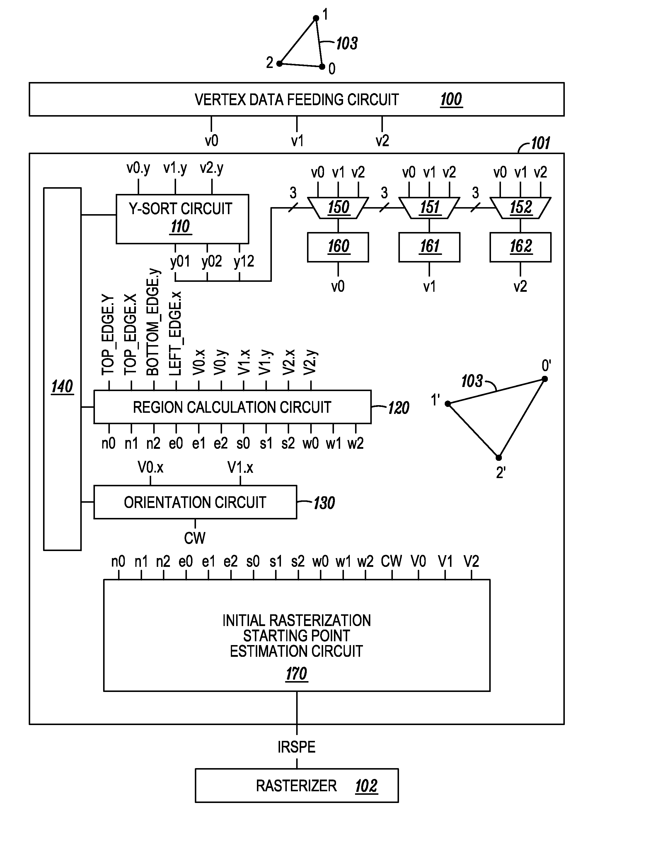
[0023]FIG. 1 shows a setup engine 101 that receives triangle vertex data v0, v1 and v2 from a vertex data feeding circuit 100, and provides data including an initial rasterization starting point estimate (“IRSPE”) to a rasterizer 102. Although the vertex data v0, v1 and v2 are shown transmitt...


PUM


Abstract

A frame buffer is divided into tiles of, for example, 32 by 32 pixels. Triangles (and portions thereof) that are within a given tile are rasterized one triangle at a time into the tile location. This process repeats for each tile in the image frame. A sorting circuit generates control bits representing a vertical order of the vertices of a current triangle. A series of multiplexers vertically sorts the vertices bases on these control bits. A region calculation circuit generates region bits representing a location each of the vertices with respect to the current tile. A trivial discard of the triangle data occurs if the region bits indicate that the entire triangle lies outside of the tile. Subsequently, an initial rasterization starting point is estimated based on the region bits to lower the time needed for the rasterizer to find the first pixel of the current triangle to be assigned values.

Description

BACKGROUND OF THE INVENTION[0001]An image typically includes several objects (e.g., a tree, sky or animated character). Each object may be computer represented by a group of triangles. Vertex data for each triangle includes x and y-coordinate data defining the position of each vertex of the triangle within the image. In three-dimensional applications, the vertex data also includes z-coordinate data which defines the depth of the triangle in virtual space. On a display, a triangle having a greater depth may be obscured by a triangle having a lesser depth, thereby giving the appearance that the image is three-dimensional.[0002]In writing each image frame, a graphics processor feeds triangle data, one triangle at a time, to a rasterizer which assigns luminance and color values to each pixel location within the triangle. After all triangles of the image frame are written into a frame buffer, the image frame is displayed. In typical graphics applications, an image frame may include many ...

Claims


Application Information

Patent Timeline
IPC IPC(8): G06T11/00G06T11/20
CPCG06T15/005
Inventor YUE, LORDSON L.BATTLE, JAMES T.
Owner QUALCOMM INC
Why Eureka
Try Eureka