
Anti-shake apparatus

a technology of anti-shake and apparatus, applied in the field of anti-shake apparatus, can solve the problems of not being able to perform the adjustment operation for accurate position-detecting operation, and the corresponding adjustment operation is not performed, so as to achieve the effect of maximizing the width and maximizing the width

Inactive Publication Date: 2007-05-29
RICOH IMAGING COMPANY
View PDF8 Cites 29 Cited by
  • Summary
  • Abstract
  • Description
  • Claims
  • Application Information

AI Technical Summary

Benefits of technology

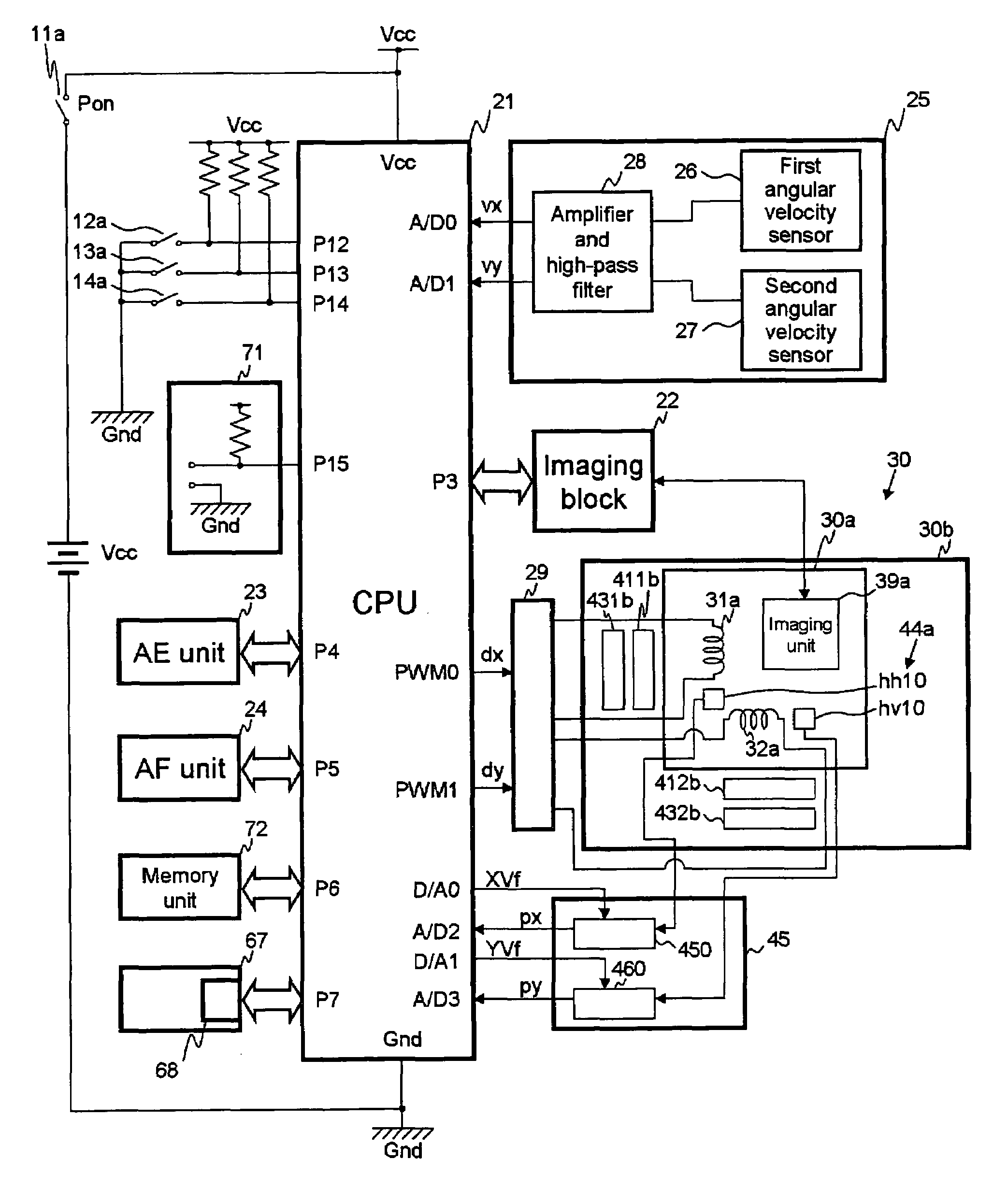
[0015]The control unit calculates the first location on the basis of an A / D converting operation by the first A / D converter, for the first detected-position signal, and calculates the second location on the basis of an A / D converting operation by the second A / D converter, for the second detected-position signal. The control unit also performs an adjusting operation which maximizes a width between minimum and maximum values of the first detected-position signal, in a horizontal movement range of the movable unit, and in an A / D converting range of the first A / D converter, and maximizes a width between minimum and maximum values of the second detected-position signal, in a vertical movement range of the movable unit, and in an A / D converting range of the second A / D converter.

Problems solved by technology

However, an adjustment operation for an accurate position-detecting operation corresponding to the change of the focal distance, such as when using a zoom lens etc., is not performed.

Method used


Image

  • Anti-shake apparatus
  • Anti-shake apparatus
  • Anti-shake apparatus

Examples


Embodiment Construction

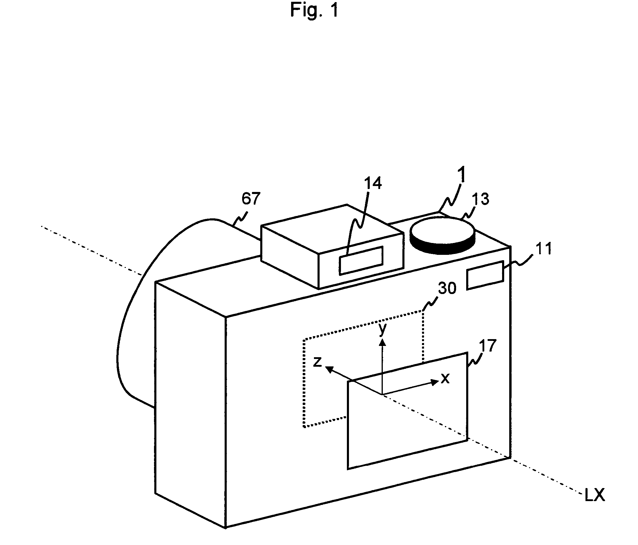
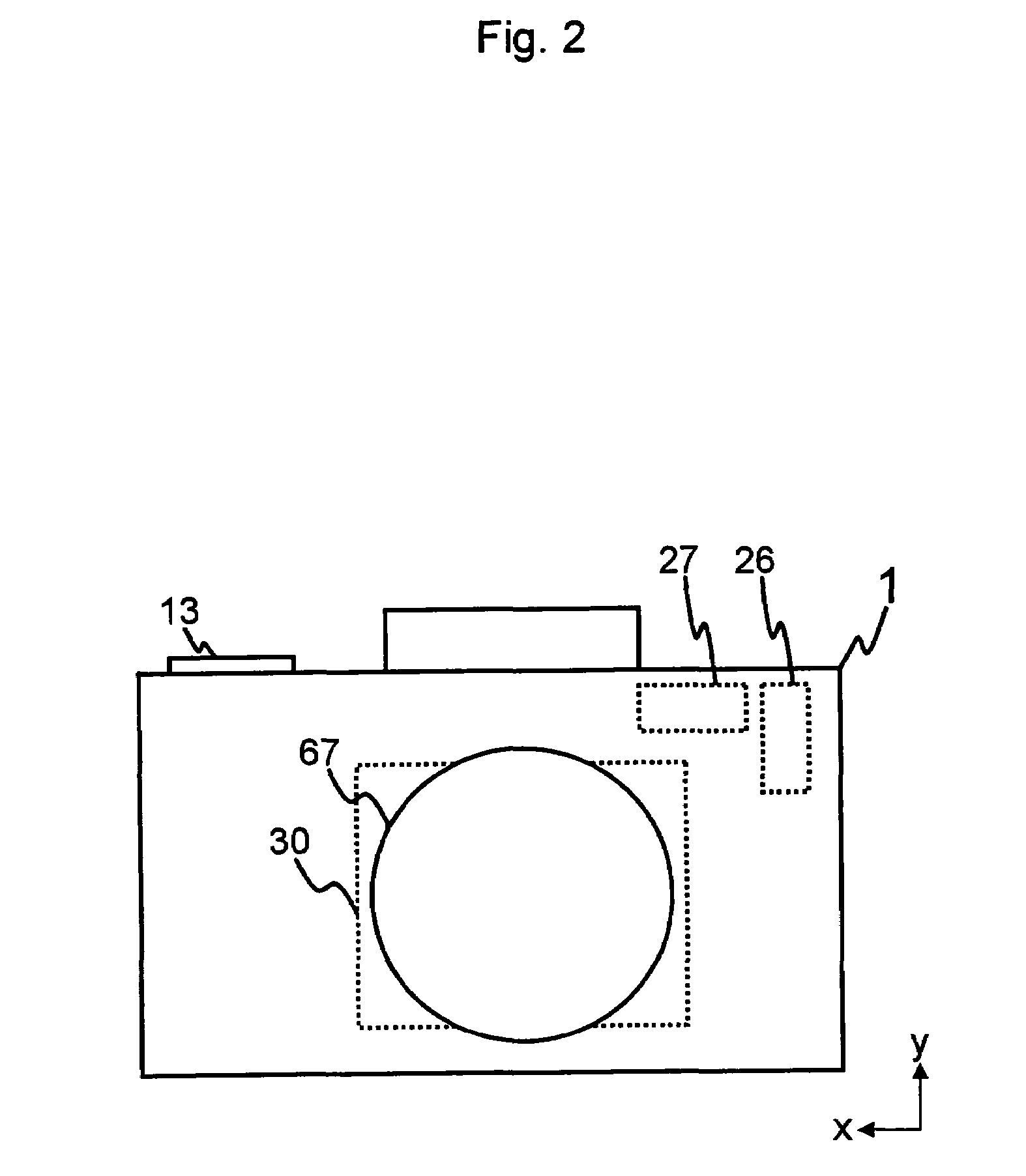
[0033]The present invention is described below with reference to the embodiment shown in the drawings. In this embodiment, the photographing apparatus 1 is a digital camera. The photographing apparatus 1 has an optical axis LX.

[0034]In order to explain the direction in these embodiments, a first direction x, a second direction y, and a third direction z are defined (see FIG. 1). The first direction x is a horizontal direction which is perpendicular to the optical axis LX. The second direction y is a vertical direction which is perpendicular to the optical axis LX and the first direction x. The third direction z is a horizontal direction which is parallel to the optical axis LX and perpendicular to both the first direction x and the second direction y.

[0035]FIG. 5 shows a construction diagram of the section along line A—A of FIG. 4.

[0036]The imaging part of the photographing apparatus 1 comprises a Pon button 11, a Pon switch 11a, a photometric switch 12a, a release button 13, a rele...


PUM


Abstract

An anti-shake apparatus of a photographing apparatus includes a signal processor. A fixed unit slidably supports, in perpendicular first and second directions, a movable unit having an imaging device or a hand-shake correcting lens. The movable unit or fixed unit has a magnetic-field change detector which has a horizontal magnetic-field change-detecting element for detecting a first location and a vertical magnetic-field change-detecting element for detecting a second location. Another of the movable unit and the fixed unit has a position-detecting magnet unit which faces the magnetic-field change detector. The signal processor outputs a first detected-position signal and a second detected-position signal. The controller calculates the first location for the first detected-position signal and the second location for the second detected-position signal. The controller maximizes a width between minimum and maximum values of the first detected-position signal and between minimum and maximum values of the second detected-position signal.

Description

BACKGROUND OF THE INVENTION[0001]1. Field of the Invention[0002]The present invention relates to an anti-shake apparatus for a photographing device (apparatus), and in particular to a position-detecting apparatus for a movable unit that includes the imaging device etc., and that can be moved for correcting the hand-shake effect.[0003]2. Description of the Related Art[0004]An anti-shake apparatus for a photographing apparatus is proposed. The anti-shake apparatus corrects for the hand-shake effect by moving a hand-shake correcting lens or an imaging device on a plane that is perpendicular to the optical axis, corresponding to the amount of hand-shake which occurs during imaging.[0005]Japanese unexamined patent publication (KOKAI) No. 2002-229090 discloses an anti-shake apparatus for a photographing apparatus. The anti-shake apparatus performs a moving operation of a movable unit, which includes a hand-shake correcting lens, by using a permanent magnet and a coil, and a position-detec...

Claims


Application Information

Patent Timeline
Patent Type & Authority Patents(United States)
IPC IPC(8): G03B17/00H04N5/228G03B5/00G03B17/02H04N23/40
CPCG03B5/00H04N5/23287H04N5/23258H04N5/23248G03B2217/005H04N23/68H04N23/6812H04N23/687
Inventor UENAKA, YUKIO
Owner RICOH IMAGING COMPANY
Learn More