Multipiece allograft implant

a multi-piece, allograft technology, applied in the field of allograft implants, can solve the problems of inability to withstand long-term use, metal cages suffer from the disadvantage of drilling and tapping the vertebral endplates for insertion, and the incidence of subsidence in long-term use is not known, so as to prevent the displacement of the implan

Active Publication Date: 2007-06-05
SYNTHES USA
View PDF162 Cites 165 Cited by
  • Summary
  • Abstract
  • Description
  • Claims
  • Application Information

AI Technical Summary

Benefits of technology

[0010]The implant preferably is comprised of two or more parts. At least the first part is preferably composed of cortical bone, while at least the second part is preferably composed of cancellous bone. The implant is configured so that when inserted between the vertebrae to be treated, the cortical and cancellous parts of the allograft are positioned so that the different properties possessed by the cortical and cancellous bone may be utilized effectively. The cortical part of the allograft is aligned with the vertebrae so that it bears the majority of the forces exerted on the implant, while the cancellous bone section promotes the growth of new bone with the implant to allow the vertebrae being treated to fuse with the allograft and each other.
[0012]The implant preferably has teeth that are formed at least in the cortical section of the allograft. Teeth formed from cortical bone, being much harder and stiffer than cancellous bone, are more effective in keeping the implant from being displaced. Furthermore, since the cortical part of the implant is where most of the load bearing occurs, teeth formed in this part have the greatest ability to grip into the vertebrae surfaces. Teeth may also be formed in portions of or the entire cancellous bone section or sections.

Problems solved by technology

A number of medical conditions, such as compression of spinal cord nerve roots, degenerative disc disease, and trauma can cause severe back pain.
Metallic cages suffer from the disadvantage of requiring drilling and tapping of the vertebral endplates for insertion.
In addition, the incidence of subsidence in long term use is not known.
Due to MRI incompatibility of metallic cages, determining fusion is problematic.
Most allografts are simply sections of bone which, although cut to the approximate height of the disc being replaced, have not been sized and / or machined on the exterior surface to have a uniform shape.
As a result, the fusion of the vertebral bodies does not occur in optimal anatomic position or in a consistent manner along the surface of the endplates.
While a surgeon may do some minimal intraoperative shaping and sizing to customize the allograft for the patient's spinal anatomy, significant shaping and sizing of the allograft during the procedure is not possible due to the nature of the allograft.
Even if extensive shaping and sizing were possible, a surgeon's ability to manually shape and size the allograft to the desired dimensions is limited.
Additionally, the strain to failure of cancellous bone is about 5–7%, while cortical bone can only withstand 1–3% strain before failure.
It should also be noted that these mechanical characteristics may degrade as a result of numerous factors such as any chemical treatment applied to the bone material, and the manner of storage after harvesting but prior to implantation (i.e. drying of bones).

Method used


Image

  • Multipiece allograft implant
  • Multipiece allograft implant
  • Multipiece allograft implant

Examples


Embodiment Construction

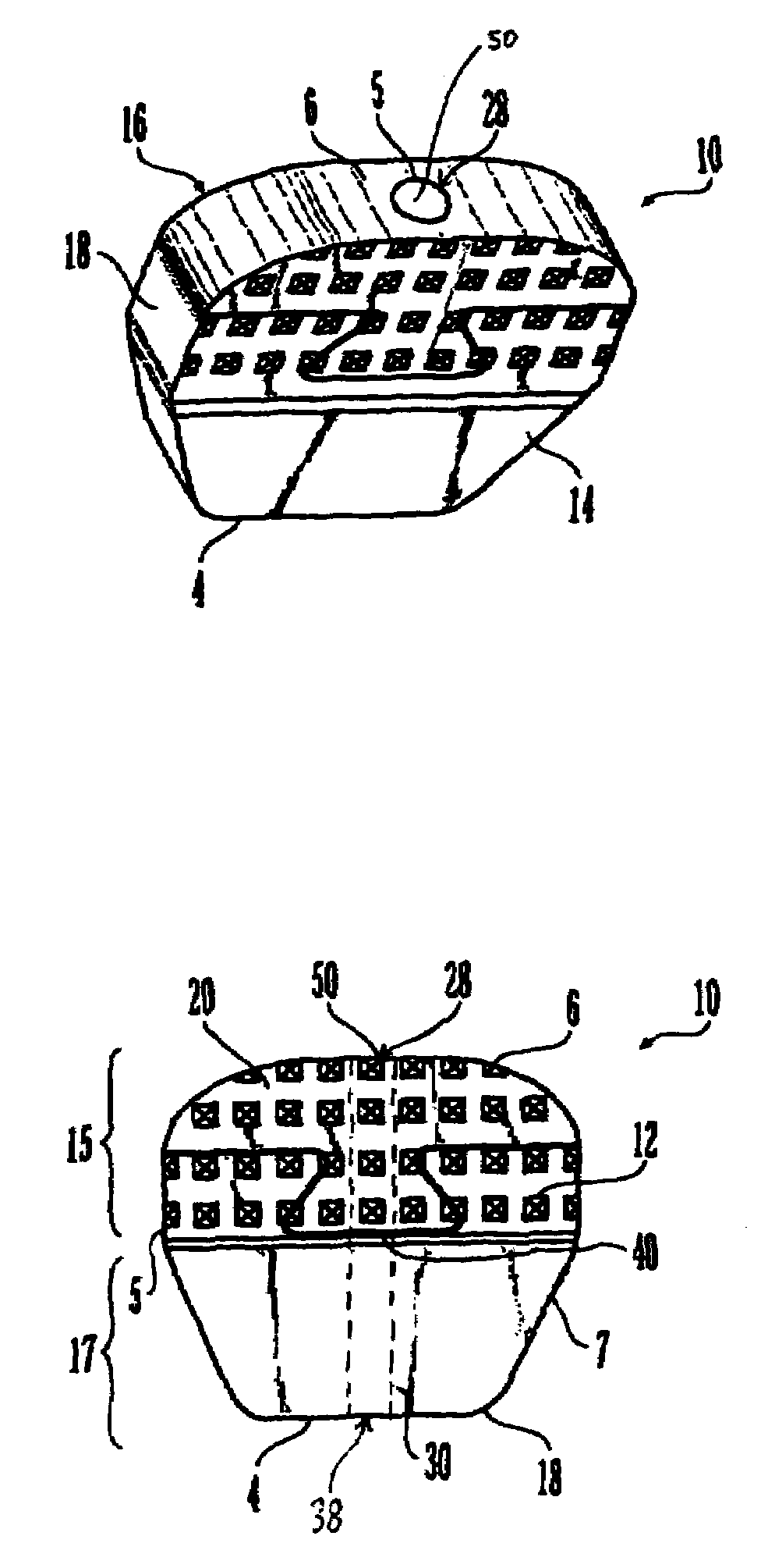
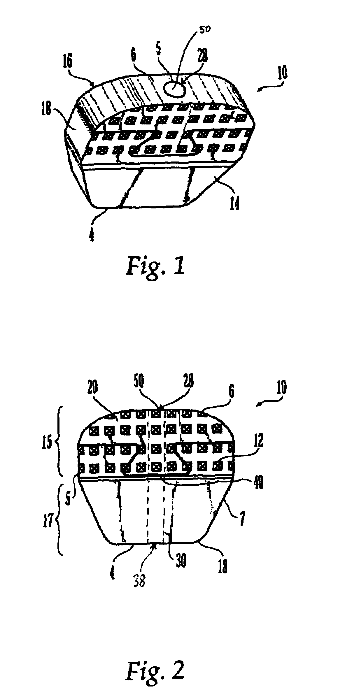
[0027]FIG. 1 shows a perspective view of a first embodiment of an intervertebral allograft spacer or implant 10 according to the present invention. Implant 10 preferably is shaped to conform in size and shape with at least a portion of the end plates of the vertebrae between which implant 10 is to be used. The outer periphery of implant 10 may be sided and shaped to match the outer periphery of the end plates of the vertebrae between which the implant 10 is to be used. Alternatively the outer periphery of the implant 10 may be sided and shaped to match only a portion of the outer periphery of the end plates of the vertebrae, or it may have an outer periphery that may not match the peripheral shape of the end plates of the vertebrae at any location.

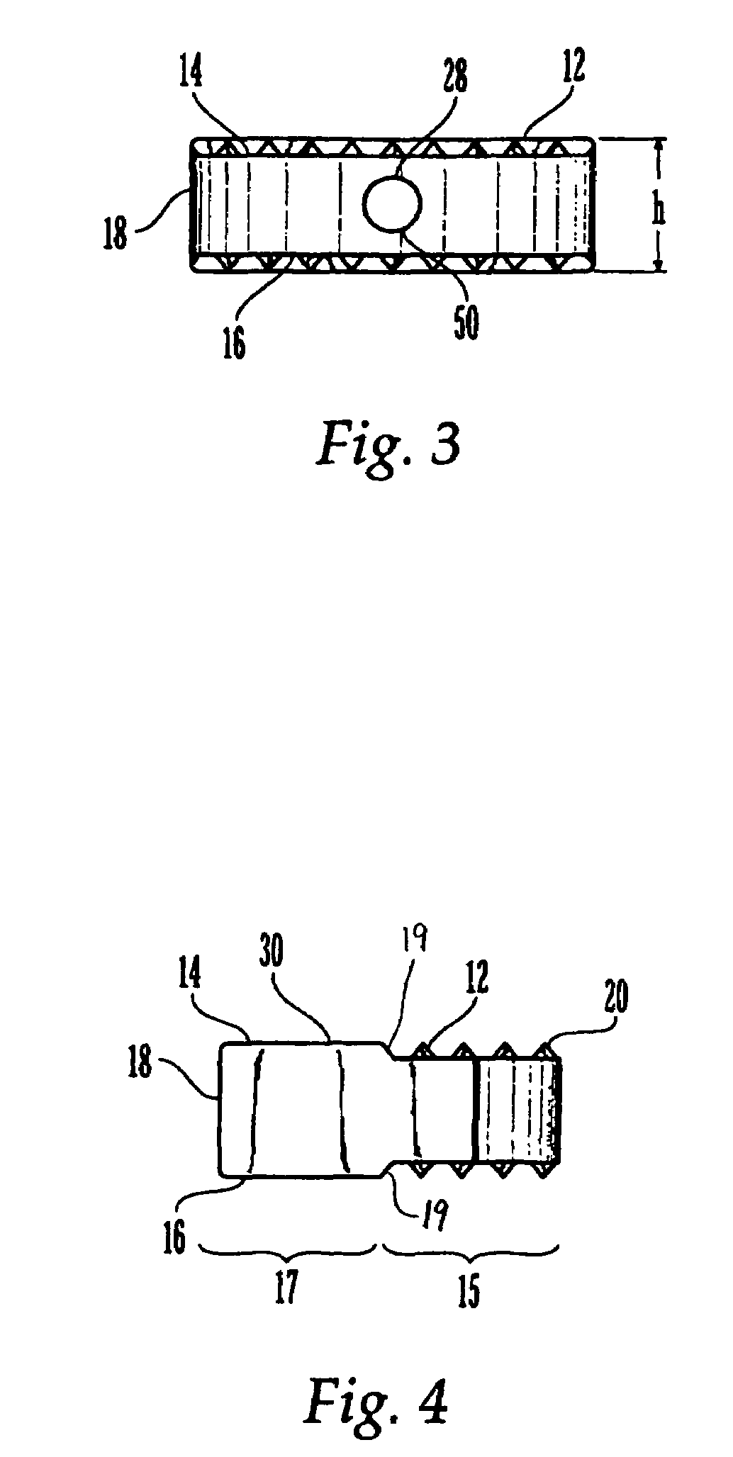
[0028]Implant 10 generally comprises a superior surface 14, an inferior surface 16, and an exterior surface 18. Superior surface 14 and inferior surface 16 further may comprise toothed sections 15 and flat sections 17. Toothed sections 15 ...


PUM


Abstract

An allogenic implant for use in intervertebral fusion is formed from two parts. The first part, composed of cortical bone, provides mechanical strength to the implant, allowing the proper distance between the vertebrae being treated to be maintained. The second part, composed of cancellous bone, is ductile and promotes the growth of new bone between the vertebrae being treated and the implant, thus fusing the vertebrae to the implant and to each other. The implant is sized and shaped to conform to the space between the vertebrae. Teeth formed on the superior and inferior surfaces of the implant prevent short-term slippage of the implant.

Description

FIELD OF THE INVENTION[0001]The present invention is directed to an allogenic implant and, more particularly, to an allogenic intervertebral implant for the fusion of vertebrae.BACKGROUND OF THE INVENTION[0002]A number of medical conditions, such as compression of spinal cord nerve roots, degenerative disc disease, and trauma can cause severe back pain. Intervertebral fusion is a surgical method of alleviating back pain. In intervertebral fusion, two adjacent vertebral bodies are fused together by removing the affected intervertebral disc and inserting an implant that would allow for bone to grow between the two vertebral bodies to bridge the gap left by the removed disc.[0003]A number of different implants and implant materials have been used for fusion with varying success. Current implants for intevertebral fusion include metallic cages and allografts. Metallic cages suffer from the disadvantage of requiring drilling and tapping of the vertebral endplates for insertion. In additi...

Claims


Application Information

Patent Timeline
Patent Type & Authority Patents(United States)
IPC IPC(8): A61F2/44A61F2/00A61F2/28A61F2/30
CPCA61F2/28A61F2/4455A61F2002/30014A61F2002/30032A61F2002/30057A61F2002/30387A61F2002/30448A61F2002/30492A61F2002/30604A61F2002/30843A61F2002/30904A61F2220/0025A61F2220/005A61F2250/0018A61F2250/003
Inventor MESSERLI, DOMINIQUEMYER, JACQUELINEBOYER, II, MICHAEL L.ANGELUCCI, CHRISTOPHER H.
Owner SYNTHES USA
Why Eureka
Try Eureka